
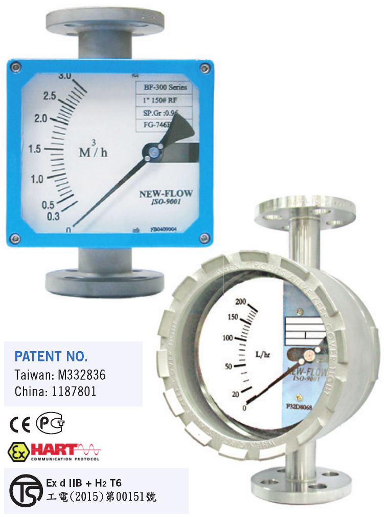
Metal Tube Flow Meter BF300
Technical Data
BF300 for high flows of gas, liquid and steam
- Case material
- Aluminium alloy case with paint; SS316 available.
- Body wetted parts
- SS316; SS316 + PTFE lining with PVDF float; others on request. Indication via magnetic coupling.
- Scales calibrated
- L/h, m³/h, kg/h, %, etc.
- SS316 float ranges
- Water: 1–100,000 L/h. Air: 0.03–1,200 Nm³/h. Special ranges on request.
- PVDF float ranges
- Water: 4–10,000 L/h. Air: 0.1–450 Nm³/h in technical data; see the published standard scales below.
- Connection types
- Thread, flange, clamp and sanitary; others on request.
- Connection sizes
- ½–5 in.
- Mounting length
- 250 mm standard; 300 mm for connections larger than 3 in. Technical data specifies 300 mm for explosion-proof: see the dimension note below.
- Temperature
- −50 to +200°C standard; up to 400°C on request.
- Protection class
- IP66 or explosion-proof: Class I, Groups B, C, D; Class II, Groups E, F, G; NEMA 4, 7, 9, depending on housing.
- Accuracy
- ±2% F.S.; ±1.6% F.S. option. Small ranges have ±5% F.S. accuracy; see the scale tables.
- Maximum pressure
- 40 kg/cm² standard; up to 100 kg/cm² optional.
- Options
- Adjustable micro, reed or inductive alarm switch; two-wire 4–20 mA analogue output.
- LCD display
- Available.
- HART communication
- Two-wire transmitter with HART protocol, galvanic isolation; suitable for SIL 2 installations.
Dimensions — mm
Swipe across each drawing to see all dimensions.
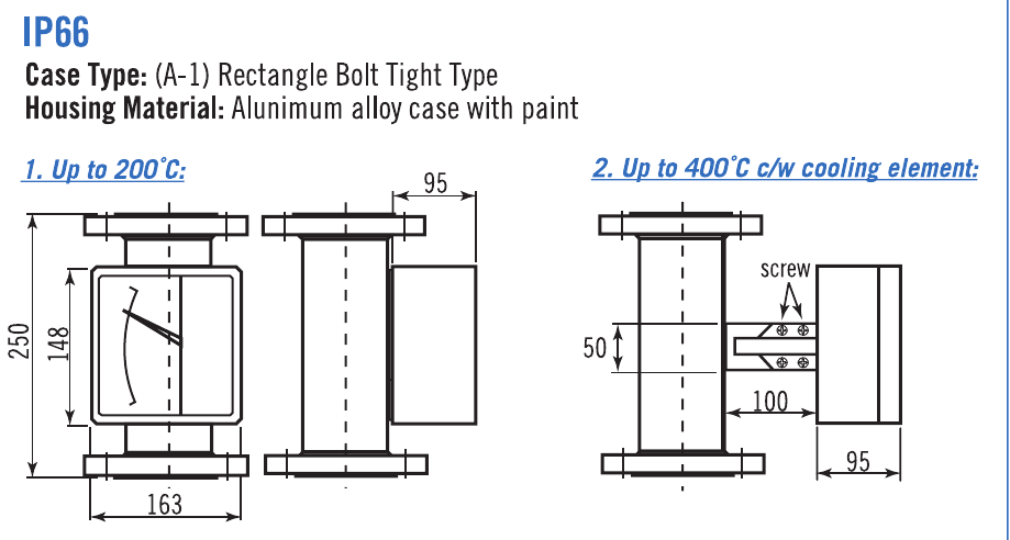
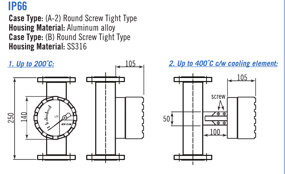
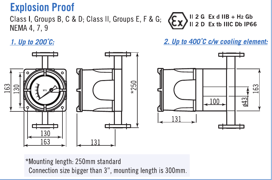
Mounting length needs confirmation for explosion-proof models: the technical data states 300 mm, while the dimension drawing states 250 mm standard (300 mm for connections larger than 3 in).
Alarm / Analog Output
BF300 / GS-M (Micro Switch)
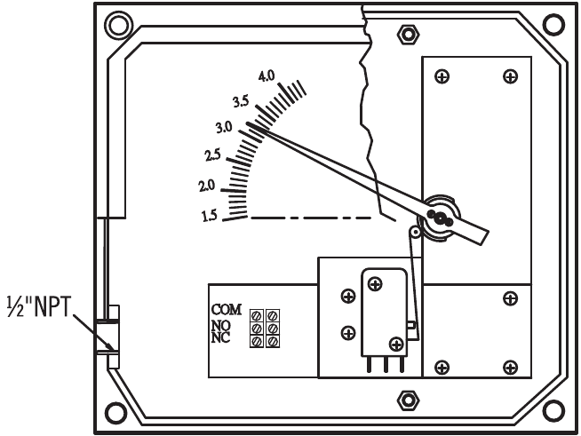
One adjustable alarm contact
Load: 5 A / 125 VAC, 5 A / 250 VAC, 2 A / 30 VDC.
Ambient temperature: −25 to +100°C.
Hysteresis: ±10% F.S. (dead band).
BF300 / GT (Analog Output)
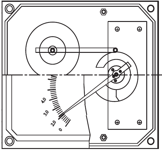
Two-wire 4–20 mA analogue output.
No alarm switch available.
Power supply: 24 VDC.
The source prints an ambient temperature of +25 to +100°C for GT. Confirm the required ambient range with your enquiry.
BF300 / GS-C (Inductive Switch)
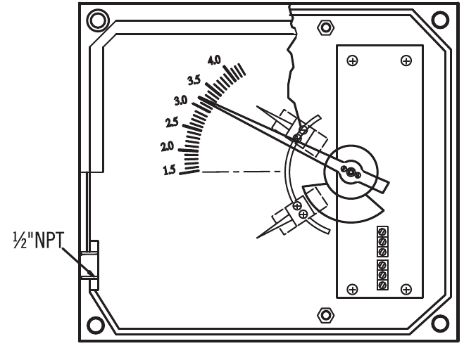
Adjustable inductive alarm switch.
Hysteresis: ±1% F.S. (dead band).
3.5 mm slotted sensor.
Two-wire DC to DIN 19234 (NAMUR), for use in hazardous areas.
Power supply: 8 VDC (Ri approximately 1 kΩ).
Current consumption: 3 mA / 1 mA.
Ambient temperature: −25 to +100°C.
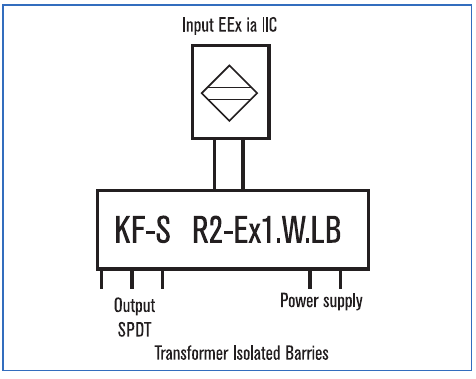
Isolated barrier output relay
Rail mounting; control circuit EEx ia IIC.
EMC to NAMUR NE21.
Contact loading: 250 VAC 2 A SPDT / 40 VDC 2 A.
1 adjustable alarm
Setpoint within 10–100% F.S.
24 VDC: KFD2-SR2-Ex1.W
115 VAC: KFA5-SR2-Ex1.W
230 VAC: KFA6-SR2-Ex1.W
2 adjustable alarms
Setpoints require a gap of 65% F.S.
24 VDC: KFD2-SR2-Ex2.W
115 VAC: KFA5-SR2-Ex2.W
230 VAC: KFA6-SR2-Ex2.W
BF300 / GS-R (Reed Switch)
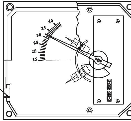
One or two setting points; Form A bistable, normally open.
Hysteresis: ±10% F.S. (dead band).
Switch rating: AC 125 V 0.5 A / DC 100 V 10 W / max. DC 250 V <40 mA.
1 adjustable alarm: Setpoint within 10–100% F.S.
2 adjustable alarms: Setpoints require a gap of 40% F.S.
Damping and principle
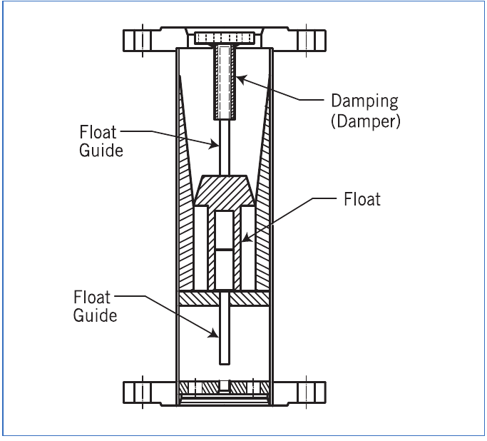
Mechanical damping — optional function
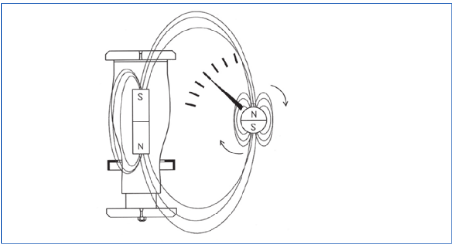
Magnetic indication principle
Standard Scales
A. SS316 float — SS316L available
| Tube | L/h Water 20°C | Nm³/h Air 0°C, 1.013 bar | Pressure loss mm water | Connection | Accuracy |
|---|---|---|---|---|---|
| BF300a | 1–10 | 0.03–0.3 | ≤750 | ½″ | ±5% F.S. |
| BF300b | 1.8–18 | 0.06–0.6 | ≤750 | ½″ | ±5% F.S. |
| BF3001 | 2.5–25 | 0.075–0.75 | ≤750 | ½″ | ±5% F.S. |
| BF3002 | 4–40 | 0.13–1.3 | ≤750 | ½″ | ±5% F.S. |
| BF3003 | 5.5–55 | 0.17–1.7 | ≤750 | ½″ | ±5% F.S. |
| BF3004 | 8–80 | 0.2–2 | ≤750 | ½″ | ±2% F.S. |
| BF3005 | 16–160 | 0.5–5 | ≤750 | ½″ | ±2% F.S. |
| BF3006 | 18–180 | 0.6–6 | ≤750 | ½″ | ±2% F.S. |
| BF3007 | 30–300 | 1–10 | ≤750 | ½″ | ±2% F.S. |
| BF3008 | 50–500 | 1.5–1.5 * | ≤750 | ½″ | ±2% F.S. |
| BF3009 | 60–600 | 1.8–18 | ≤750 | ½″ | ±2% F.S. |
| BF3010 | 70–700 | 2–20 | ≤750 | ½″ | ±2% F.S. |
| BF3011 | 100–1000 | 3–30 | ≤750 | ¾″ | ±2% F.S. |
| BF3012 | 120–1200 | 4–40 | ≤750 | 1″ | ±2% F.S. |
| BF3013 | 160–1600 | 5–50 | ≤700 | 1″ | ±2% F.S. |
| BF3014 | 200–2000 | 6–60 | ≤700 | 1″ | ±2% F.S. |
| BF3015 | 240–2400 | 7–70 | ≤700 | 1″ | ±2% F.S. |
| BF3016 | 280–2800 | 8.5–85 | ≤700 | 1″ | ±2% F.S. |
| BF3017 | 320–3200 | 9–90 | ≤700 | 1″ | ±2% F.S. |
| BF3018 | 350–3500 | 10–100 | ≤700 | 1″ | ±2% F.S. |
| BF3019 | 500–5000 | 14–140 | ≤650 | 1½″ | ±2% F.S. |
| BF3020 | 600–6000 | 15–150 | ≤650 | 1½″ | ±2% F.S. |
| BF3021 | 700–7000 | 20–200 | ≤650 | 1½″ | ±2% F.S. |
| BF3022 | 800–8000 | 24–240 | ≤650 | 1½″ | ±2% F.S. |
| BF3023 | 1000–10000 | 30–300 | ≤650 | 2″ | ±2% F.S. |
| BF3024 | 1200–12000 | 35–350 | ≤650 | 2″ | ±2% F.S. |
| BF3025 | 1400–14000 | 40–400 | ≤650 | 2″ | ±2% F.S. |
| BF3026 | 1500–15000 | 45–450 | ≤1000 | 2″ | ±2% F.S. |
| BF3027 | 1800–18000 | 60–600 | ≤800 | 2½″ | ±2% F.S. |
| BF3028 | 2000–20000 | 75–750 | ≤800 | 2½″ | ±2% F.S. |
| BF3029 | 2300–23000 | 90–900 | ≤850 | 3″ | ±2% F.S. |
| BF3030 | 2500–25000 | 120–1200 | ≤1000 | 3″ | ±2% F.S. |
| BF3031 | 2800–28000 | — | ≤1100 | 3″ | ±2% F.S. |
| BF3032 | 3000–30000 | — | ≤1200 | 3″ | ±2% F.S. |
| BF3033 | 3500–35000 | — | ≤1000 | 4″ | ±2% F.S. |
| BF3034 | 4000–40000 | — | ≤1000 | 4″ | ±2% F.S. |
| BF3035 | 5000–50000 | — | ≤1200 | 4″ | ±2% F.S. |
| BF3036 | 6000–60000 | — | ≤1500 | 4″ | ±2% F.S. |
| BF3037 | 10000–100000 | — | ≤2500 | 5″ | ±2% F.S. |
B. PVDF float — SS316 + PTFE-lined wetted parts only
| Tube | L/h Water 20°C | Nm³/h Air 0°C, 1.013 bar | Pressure loss mm water | Connection | Accuracy |
|---|---|---|---|---|---|
| BF3001P | 4–40 | 0.13–1.3 | ≤750 | ½″ | ±5% F.S. |
| BF3002P | 5.5–55 | 0.17–1.7 | ≤750 | ½″ | ±5% F.S. |
| BF3003P | 8–80 | 0.2–2 | ≤750 | ½″ | ±2% F.S. † |
| BF3004P | 16–160 | 0.5–5 | ≤750 | ½″ | ±2% F.S. |
| BF3005P | 28–280 | 0.9–9 | ≤750 | ¾″ | ±2% F.S. |
| BF3006P | 35–350 | 1.1–11 | ≤750 | ¾″ | ±2% F.S. |
| BF3007P | 40–400 | 1.3–13 | ≤750 | ¾″ | ±2% F.S. |
| BF3008P | 50–500 | 1.5–15 | ≤750 | 1″ | ±2% F.S. |
| BF3009P | 70–700 | 2–20 | ≤700 | 1″ | ±2% F.S. |
| BF3010P | 90–900 | 2.5–25 | ≤700 | 1″ | ±2% F.S. |
| BF3011P | 100–1000 | 3–30 | ≤700 | 1″ | ±2% F.S. |
| BF3012P | 120–1200 | 4–40 | ≤700 | 1″ | ±2% F.S. |
| BF3013P | 160–1600 | 5–50 | ≤700 | 1″ | ±2% F.S. |
| BF3014P | 200–2000 | 6–60 | ≤700 | 1″ | ±2% F.S. |
| BF3015P | 250–2500 | 7–70 | ≤650 | 1″ | ±2% F.S. |
| BF3016P | 300–3000 | 9–90 | ≤650 | 1½″ | ±2% F.S. |
| BF3017P | 350–3500 | 10–100 | ≤650 | 1½″ | ±2% F.S. |
| BF3018P | 450–4500 | 12–120 | ≤650 | 1½″ | ±2% F.S. |
| BF3019P | 450–4500 | 13–135 | ≤650 | 1½″ | ±2% F.S. |
| BF3020P | 500–5000 | 14–140 | ≤650 | 1½″ | ±2% F.S. |
| BF3021P | 650–6500 | 18–180 | ≤650 | 2″ | ±2% F.S. |
| BF3022P | 700–7000 | — | ≤650 | 2″ | ±2% F.S. |
| BF3023P | 800–8000 | — | ≤650 | 2″ | ±2% F.S. |
| BF3024P | 900–9000 | — | ≤650 | 2½″ | ±2% F.S. |
| BF3025P | 1000–10000 | — | ≤650 | 2½″ | ±2% F.S. |
* BF3008 air is printed as 1.5–1.5 Nm³/h. This range requires confirmation and is not offered as a standard selection.
† BF3003P accuracy is ±2% F.S. in its table row but ±5% F.S. in note 1. Confirm before ordering.
The PDF lists 2½ in scales but no 2½ in connection ordering code; request advice for those sizes. ±1.6% F.S. accuracy is available on request. Technical data are subject to change.
Build your BF300 ordering code
Select the options in the same order as the PDF. Each choice shows its ordering code.