
D118 Ultrasonic Flowmeter
Digital Correlation Transit Time Flowmeter
Applications and measurement
For hot, cooling, potable and sea water; petroleum products; chemicals including alcohol and acids; beverage, food and pharmaceutical processing; secondary sewage and waste treatment; mining and power-plant processes; fire-suppression testing; pipeline leak detection and inspection; and flow measurement surveys.
The D118 measures liquid flow by comparing upstream and downstream ultrasonic transit times. It is principally for full-pipe clean liquids, with tolerance for small amounts of air bubbles or suspended solids. It supports configured pipe liners and a range of pipe materials and liquids. Pipe sizes span 25–5000 mm, with standard and high-temperature clamp-on or insertion transducers, SD-card logging and optional RTD temperature input.
About D118
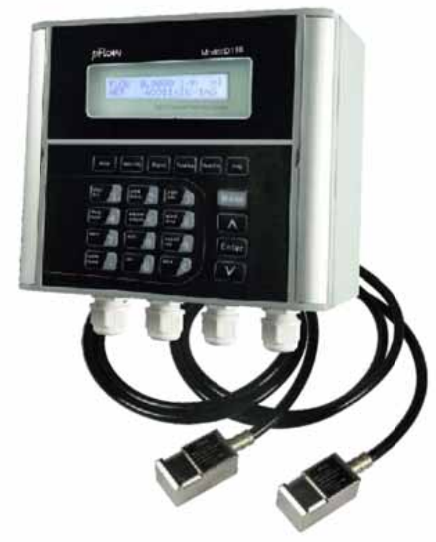
D118 Ultrasonic Flowmeter is a state-of-the-art transit time ultrasonic flowmeter.
Designed using the latest digital technology and low-voltage broadband pulse transmission.
Comparing with other traditional flowmeter or ultrasonic flowmeter, it has distinctive features such as high precision, high reliability, high capability and low cost, other features:
- TVT technology designed.
- Less hardware components, low voltage broadband pulse transmission, low consumption power.
- Clear, user-friendly menu selections make flowmeter simple and convenient to use.
- Daily, monthly and yearly totalized flow
- Parallel operation of positive, negative and net flow totalizes with scale factor (span) and 7 digit display, while the output of totalize pulse and frequency output are transmitted via relay and open collector.
Application and Installation Guidance
Pipe and liner suitability
Preconfigured pipe materials: Carbon Steel, Stainless Steel, Cast Iron, Ductile Iron, Copper, PVC, Aluminum, Asbestos and Fiber Glass-Epoxy. For other materials, select “other” in the meter and enter the material’s sound velocity. Additional settings may be available in the full manual or from a suitable material reference.
The pipe must conduct sound. HDPE is not generally recommended by the manufacturer: thick walls can prevent adequate signal transmission. Walls thicker than approximately 20 mm may cause signal issues; this is a rough guide, not a guarantee of HDPE compatibility.
Lined pipes can be measured when configured accordingly. Liner presets: None/No Liner, Tar Epoxy, Rubber, Mortar, Polypropylene, Polystyrol, Polystyrene, Polyester, Polyethylene, Ebonite and Teflon. For other liners, select “other” and enter the material’s sound velocity; consult the full manual or a suitable material reference for settings.
Liquid selection
Use clean liquids with little or no particles or entrained air. Clean does not mean transparent: oil can be suitable. Excessive suspended solids prevent operation; approximately 5% is a guide, with the limit varying by application.
Liquid presets: water, sea water, kerosene, gasoline, fuel oil, crude oil, propane, butane, diesel oil, castor oil, peanut oil, gasoline #90, gasoline #93 and alcohol. For other liquids, select “other” and enter fluid sound velocity and viscosity, using the full manual or a suitable fluid reference.
Accurate settings are essential: the further the entered sound velocity is from the actual value, the poorer the accuracy; measurement may fail entirely.
Measurement location
Choose fully developed, stable, laminar flow and avoid turbulent areas. The pipe must remain full because the signal cannot pass through air. Use an upward-flowing vertical pipe or a full horizontal pipe.
On horizontal pipes, mount transducers at the sides to avoid air or gas at the top and sediment at the bottom. A general guide is 10 pipe diameters upstream and 5 downstream; requirements vary with the installation. Follow Installation Site Selection below.
Setup and mounting
Enter pipe outside diameter, wall thickness, material, liner details where applicable and liquid type into the meter to obtain the required transducer spacing. Apply couplant grease generously to the sensing faces and mount the transducers at that spacing.
The supplied reference describes included couplant and metal straps for pipes up to approximately 300 mm outside diameter, with optional, extra-cost ratchet straps for larger pipes.
Response time and limitations
Allow at least a few seconds for the signal to stabilise and show accurate readings. Intermittent flow, such as a pump running for 20 seconds then stopping, and diaphragm-pump flow are not ideal.
Damping is enabled by default to average and stabilise the display. The reference recommends 3–10 seconds; setting it to zero gives a faster response to flow changes.
Accurate low dosing and custody-transfer applications are unsuitable: some totalised flow can be missed while the signal attenuates and the measurement ramps up, depending on damping.
Application review
If suitability is uncertain, describe your application and email a photo of the proposed measurement site and mounting area. We can review the installation and, if necessary, suggest another meter type.
Technical Data, Dimensions and Wiring
Performance specifications
- Flow range
- ±0.03ft/s ~ ±40ft/s (±0.01m/s ~ ±12m/s)
- Accuracy
- ±0.5% of measured value (for ±1.5ft/s ~ ±40ft/s)
- Repeatability
- 0.15% of measured value
- Linearity
- ±0.5%
- Pipe size
- 1" to 200" (25mm to 5000mm)
Function specifications
- Outputs
- Analog output: 4~20mA, max load 750Ω. Pulse output: 0~9999Hz, OCT (min. and max. frequency is adjustable). Relay output: SPST, max 1Hz (1A@125VAC or 2A@30VDC).
- Communication
- RS232 & RS485; terminal Modbus Protocol.
- SD card
- Standard 2G SD card, maximum record: 512 days. Record time interval.
- Power supply
- Specification table: 90 to 245 VAC, 48 to 63 Hz, or 10 to 36 VDC. Ordering table: 90–250 VAC, 48–63 Hz, or 10–36 VDC.
- Keypad
- Specification table: 22 keys with tactile action. Ordering table: 16 (4×4) touch keys.
- Display
- 40 character, 2 line (20×2) lattice alphanumeric, back lit LCD.
- Temperature
- Transmitter: -40°F~140°F (-40°C~60°C). Transducer: -40°F~176°F (-40°C~80°C, standard).
- Humidity
- Up to 99% RH, non-condensing
Physical specifications
- Installation method
- Wall mount
- Transmitter
- NEMA 4X (IP65), die-cast aluminum. Ordering table: die-cast aluminum machined enclosure; explosion-proof enclosure option, Ex dia II BT4.
- Transducer
- Encapsulated design; double-shielded transducer cable.
- Cable length
- Standard/maximum: 30ft/1000ft (9m/305m).
- Weight
- Transmitter: approximately 2.15kg; transducer: approximately 0.9kg.
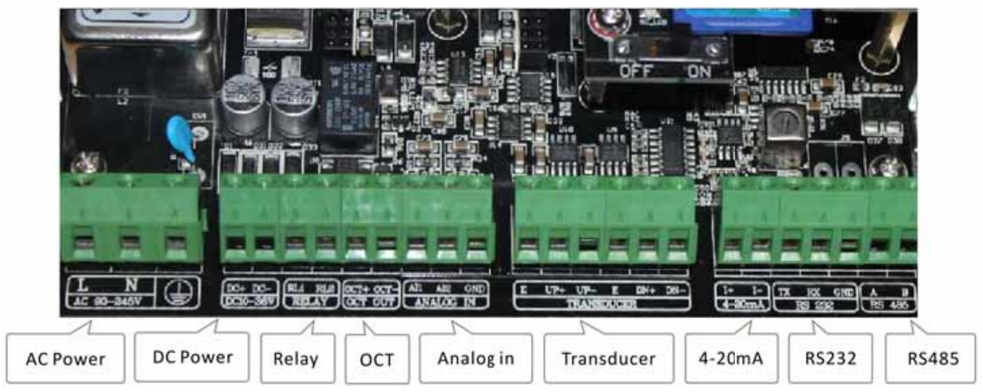
Wiring Diagram
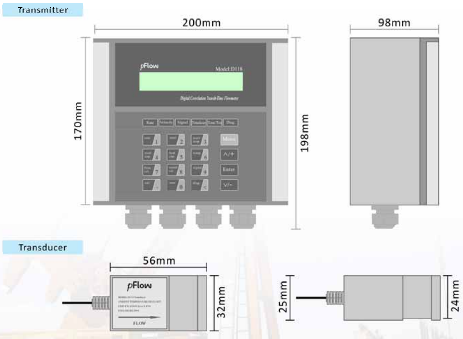
Transmitter and Transducer Dimensions — mm
Transducer Installation Methods
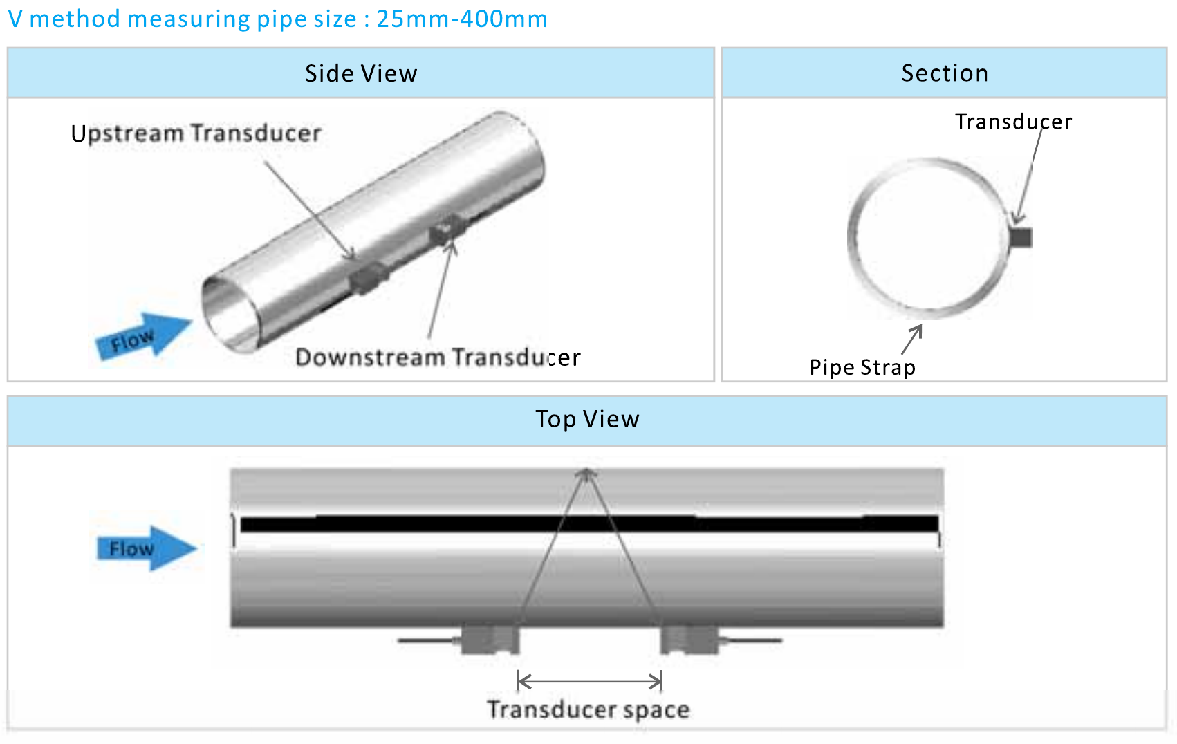
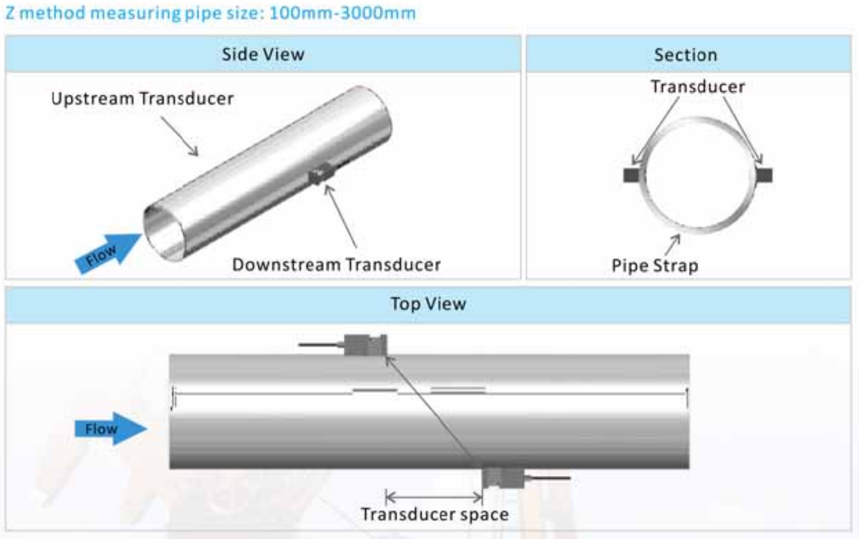
Installation Site Selection
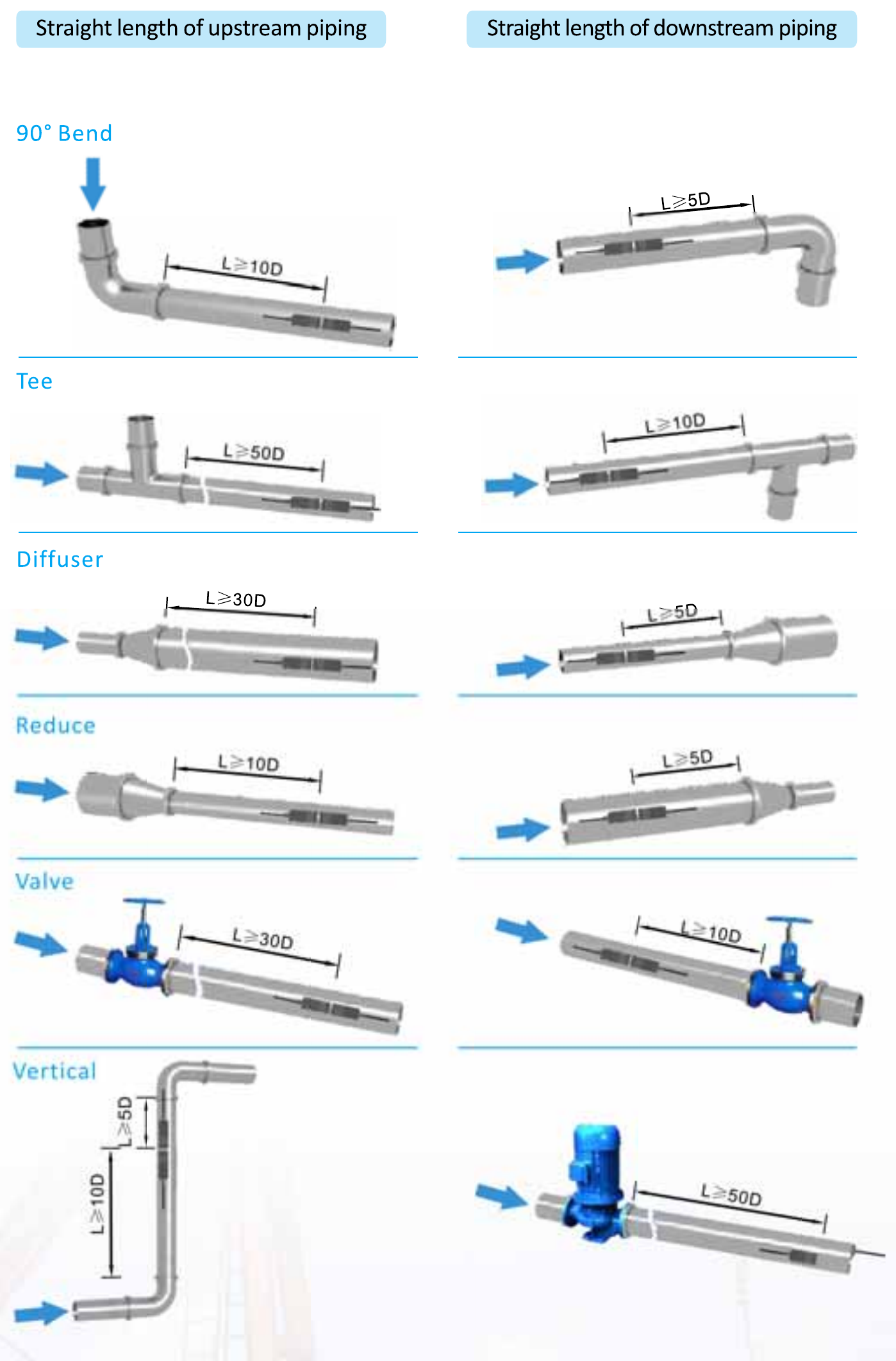
When selecting a measurement site, it is important to select an area where the fluid flow profile is fully developed to guarantee a highly accurate measurement. Use the following guidelines to select a proper installation site:
Choose a section of pipe that is always full of liquid, such as a vertical pipe with flow in the upward direction or a full horizontal pipe.
Ensure enough straight pipe length at least equal to the figure shown below for the upstream and downstream transducers installation.
Ensure that the pipe surface temperature at the measuring point is within the transducer temperature limits.
Consider the inside condition of the pipe carefully. If possible, select a section of pipe where the inside is free of excessive corrosion or scaling.
Build your D118 ordering code
Example — Standard Model: D118-1-1-C010-030
Standard enclosure with Clamp-on transducers, RS232/RS485, 9m cable.