
Sight Flow Indicators
FW-Series Impeller Flow Sight Glass Gauge
Highly visible impeller indication for threaded and flanged pipework
The FW-Series provides bilateral flow indication through a single or double window, with large-size flanged and high-pressure configurations available.
- CE 2810PED marking on request
- IECEx / ATEXOptional II 2G, Ex h IIC Tx Gb
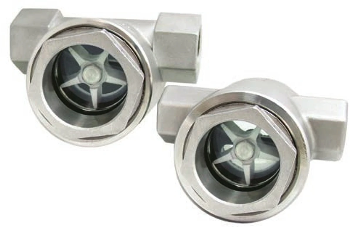 FW-1 — Single window · FW-2 — Double window
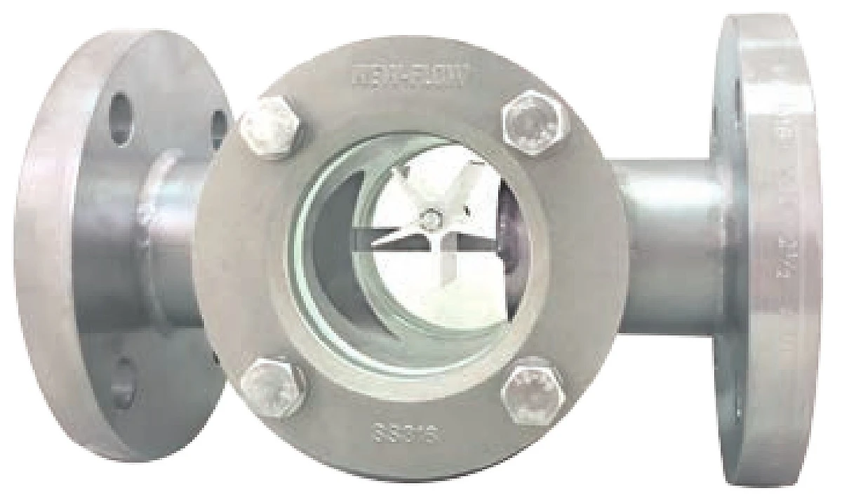 FW-3 — Flange, double window
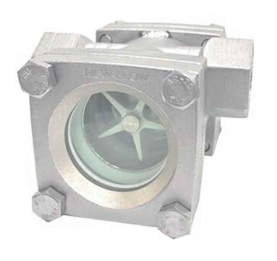 FW-4 — Double window with high pressure
Models and service
- FW-1 single window and FW-2 double window for threaded or flanged connections
- FW-3 large-size double-window flanged construction
- FW-4 double-window high-pressure construction
Technical data
Materials and indication
- Service
- Gases and liquids
- Body / wetted parts
- SS304 (CF8), SS316 (CF8M), SS316L (CF3M); Duplex UNS J92205 for FW-2, FW-3 and FW-4; WCB on request, non-Ex only
- Window
- Tempered glass
- Gasket
- Teflon or Sigma 533
- Impeller temperature ranges
- ABS (white): −25 to 70°C; PVDF (red or white): −20 to 100°C; PPS + 40% glass fibre (dark brown): 0 to 200°C
Pressure, sizes and connections
- FW-1 pressure
- 16 kg/cm² at 25°C water
- FW-2 pressure
- 16 kg/cm² at 25°C water
- FW-3 pressure
- 16, 25 or 40 kg/cm² at 25°C water
- FW-4 pressure
- 50 kg/cm² at 25°C water
- FW-1 and FW-2 sizes
- 1/4 to 2 in threaded or flanged
- FW-3 sizes
- 2 to 8 in flanged only
- FW-4 sizes
- 1/2 to 1 1/4 in; NPT female thread only
- Ex application pressure
- 0–16 kg/cm² gauge; WCB bodies are not available for Ex applications
Impeller temperature ranges apply to the rotor only. Confirm the complete body, gasket and application temperature limits.
Body, flange and cover materials
| Code | Body / flange | Cover | Models |
|---|---|---|---|
| S | SS316 (CF8M) | SS316 (CF8M) | FW-1 to FW-4 |
| S4 | SS304 (CF8) | SS304 (CF8) | FW-1 to FW-4 |
| SL | SS316L (CF3M) | SS316 (CF8M) | FW-1 to FW-4 |
| DS | Duplex UNS J92205 | SS316 (CF8M) | FW-2, FW-3, FW-4 |
| WB | WCB body / A105 flange | WCB | FW-1 to FW-4; non-Ex only |
Dimensions
Dimensions in millimetres.
FW-1 — Single window
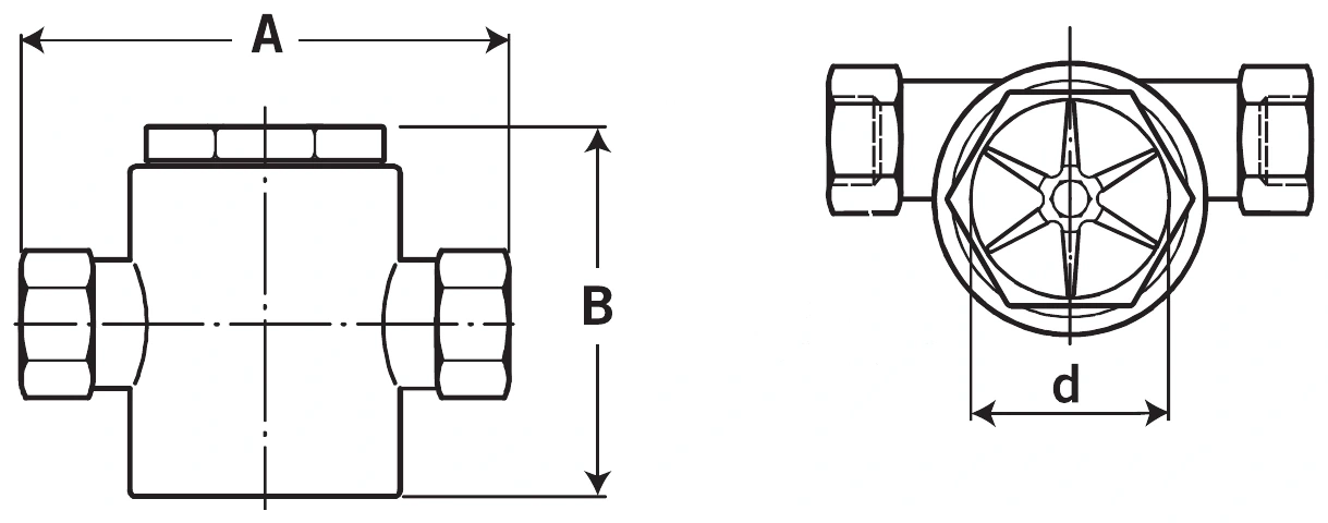
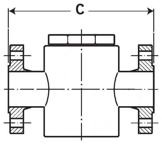
| Dimension | 1/4 in | 3/8 in | 1/2 in | 3/4 in | 1 in | 1 1/4 in | 1 1/2 in | 2 in |
|---|---|---|---|---|---|---|---|---|
| A | 76 | 76 | 100 | 100 | 109 | 109 | 150 | 150 |
| B | 43 | 43 | 67 | 67 | 72 | 72 | 95 | 95 |
| d | 32 | 32 | 40 | 40 | 40 | 40 | 57 | 57 |
| C | - | - | 130 | 130 | 160 | 200 | 200 | 220 |
| C (option) | - | - | 140 | 140 | 140 | 180 | 180 | 220 |
FW-2 — Double window
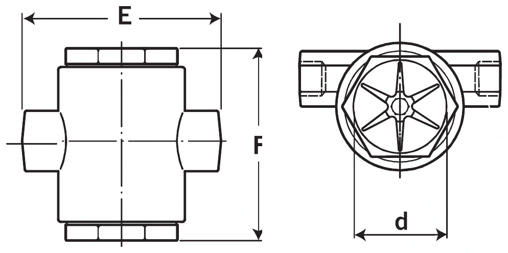
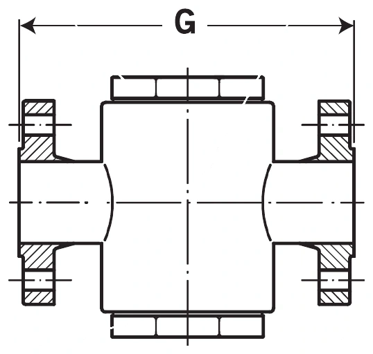
| Dimension | 1/4 in | 3/8 in | 1/2 in | 3/4 in | 1 in | 1 1/4 in | 1 1/2 in | 2 in |
|---|---|---|---|---|---|---|---|---|
| E | 76 | 76 | 100 | 100 | 109 | 109 | 150 | 150 |
| F | 70 | 70 | 80 | 80 | 96 | 96 | 110 | 110 |
| d | 32 | 32 | 40 | 40 | 40 | 40 | 57 | 57 |
| G | - | - | 130 | 130 | 160 | 200 | 200 | 220 |
| G (option) | - | - | 140 | 140 | 140 | 180 | 180 | 220 |
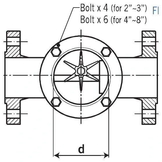
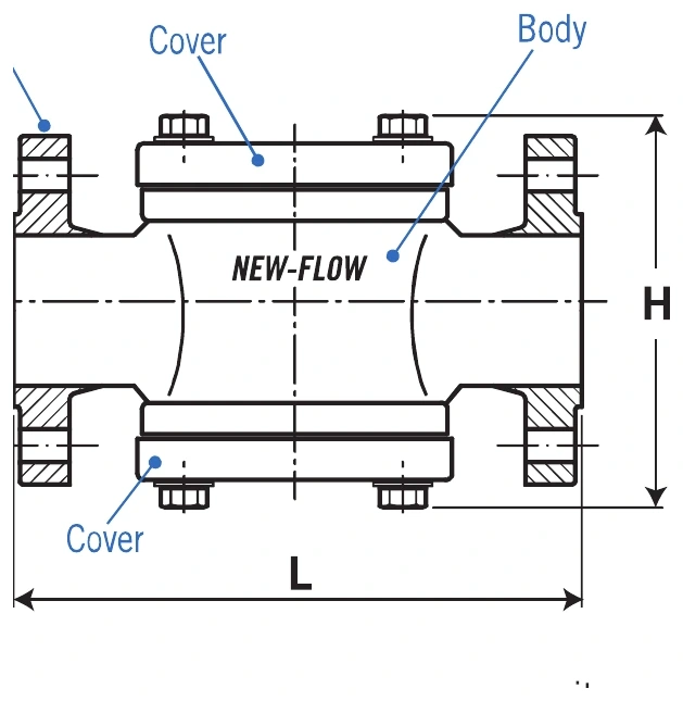
FW-3 — Large flanged double window
| Dimension | 2 in | 2 1/2 in | 3 in | 4 in | 5 in | 6 in | 8 in |
|---|---|---|---|---|---|---|---|
| d | 65 | 84 | 84 | 109 | 148 | 170 | 222 |
| H | 146 | 164 | 183 | 212 | 247 | 276 | 345 |
| L | 220 | 270 | 270 | 320 | 380 | 420 | 500 |
| L (option) | 220 | 260 | 260 | 310 | - | - | - |
| L (300 lb) | — | — | — | — | — | — | — |
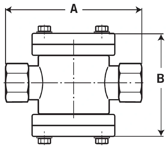
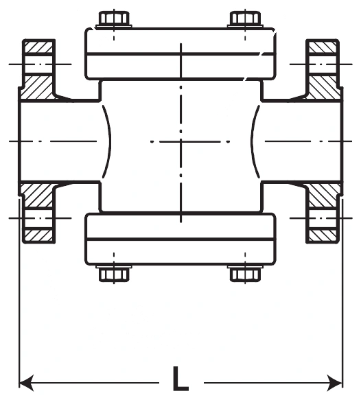
FW-4 — High-pressure double window
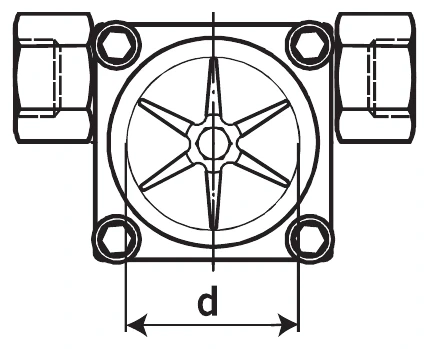
| Dimension | 1/2 in | 3/4 in | 1 in | 1 1/4 in |
|---|---|---|---|---|
| A | 100 | 100 | 109 | 109 |
| B | 100 | 100 | 110 | 110 |
| L | 130 | 130 | 160 | 200 |
| L (option) | 140 | 140 | 140 | 180 |
| d | 43 | 43 | 43 | 43 |
FW-4 is specified as NPT female thread only in Technical Data. The datasheet also includes a flanged drawing and L dimensions; flanged FW-4 requirements need confirmation.
FW-1/FW-2 flange dimensions start at ½ inch. Confirm flange dimensions for ¼ and ⅜ inch enquiries. No FW-3 L (300 lb) dimensions are supplied.
Impeller options and flow direction
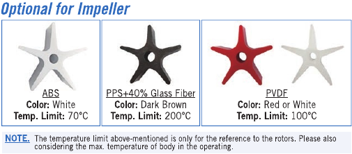
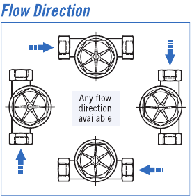
Explosion-proof certification and temperature classes
Optional IECEx and ATEX II 2G certification, Ex h IIC Tx Gb. Maximum 16 kg/cm² gauge for Ex applications. WCB is excluded.
| Class | ½–2½ inches (15A–65A) | 3 inches (80A) and larger |
|---|---|---|
| T2 | 175°C < Tprocess ≤ 270°C; Tamb ≤ 75°C | 140°C < Tprocess ≤ 220°C; Tamb ≤ 75°C |
| T3 | 110°C < Tprocess ≤ 175°C; Tamb ≤ 75°C | 85°C < Tprocess ≤ 140°C; Tamb ≤ 75°C |
| T4 | 75°C < Tprocess ≤ 110°C; Tamb ≤ 75°C | 60°C < Tprocess and Tamb ≤ 75°C; also 75°C < Tprocess ≤ 85°C and Tamb ≤ 75°C |
| T5 | 60°C < Tprocess; Tamb ≤ 75°C | 48°C < Tprocess; Tamb ≤ 60°C |
| T6 | Tprocess and Tamb ≤ 60°C | Tprocess and Tamb ≤ 48°C |
These are certification conditions, not increased impeller or body temperature ratings. Select an impeller suitable for the application.
The T4 large-size entry contains overlapping conditions and the T5 entries give no upper process-temperature bound. Confirm class suitability for the application.
The certification table does not define conditions for ¼ or ⅜ inch sizes. Ex requirements for these sizes need confirmation.
Ordering information
Choose your options to build an enquiry reference.
Flange class does not increase the model’s working-pressure limit. Ratings are at 25°C water; confirm application suitability.
WCB bodies are non-Ex only. Ex conditions for ¼ and ⅜ inch sizes are not defined; contact Sightflow for these requirements.
Specifications are general selection guidance. Confirm materials, connection standards, operating temperature and pressure with Sightflow before placing an order.