
Sight Flow Indicators
T-Series Threaded Sight Flow Indicator
Threaded spring-paddle indication for gas and liquid service
The T-Series uses a spring paddle for easy observation of flow in any direction, with double-window, double-glass and protected-glass configurations available.
- CE 2810Marking options available
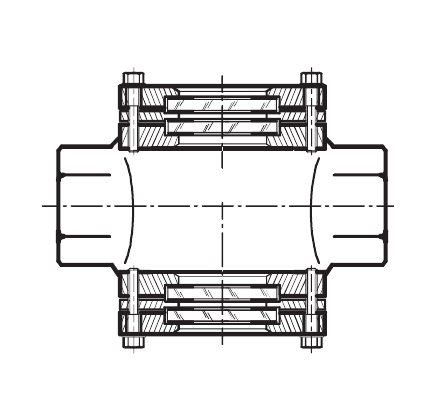
- IECEx / ATEXExplosion-proof certification option
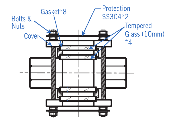
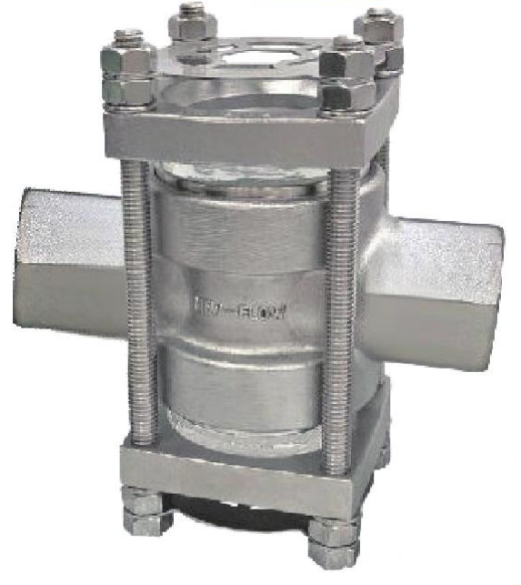 TB-DP — Protection fence
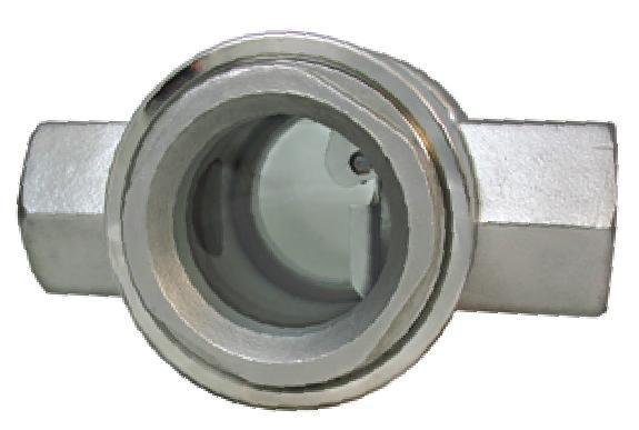 TA — Threaded type
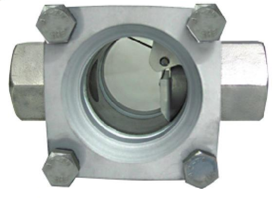 TB — Double window
Service and indication
- Compatible gas and liquid service for industrial and water-treatment systems
- Spring-paddle indication visible through tempered-glass windows
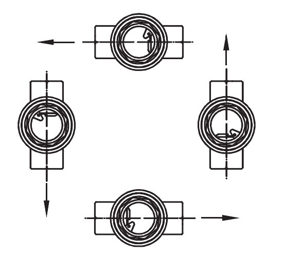
- Flow may travel horizontally in either direction or vertically upward or downward
Technical data
Materials and temperature
- Body
- SS304, SS316 or SS316L
- Paddle and spring
- SS316
- Gauge
- Tempered glass
- Gasket
- Teflon, Gore-Tex, Graphite or Sigma 533
- Maximum temperature
- 150°C with Teflon; 300°C with Gore-Tex
- TA gasket restriction
- Gore-Tex, Graphite and Sigma 533 are unsuitable for TA Type
Pressure and options
- TA maximum pressure
- 10 kg/cm² at 25°C water
- TB / TB-DG / TB-DP pressure
- 15, 25 or 40 kg/cm² at 25°C water
- Protection fence
- Optional SS304 external protection
- External tempered glass
- Optional four-piece protection
- Explosion-proof type
- 15A to 50A only; 16 kg/cm²
- Certification
- IECEx and ATEX options with temperature classification
Dimensions and mounting
Dimensions in millimetres. Mounting positions are shown alongside the model drawings; dimension data is below.
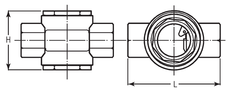
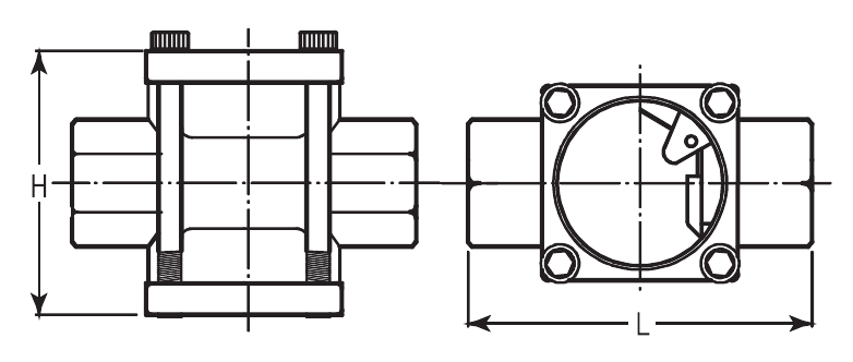
| Dimension | 15A | 20A | 25A | 40A | 50A |
|---|---|---|---|---|---|
| TA — L | 114 | 114 | 114 | 130 | 150 |
| TA — H | 72 | 72 | 72 | 120 | 136 |
| TB — L | 114 | 114 | 114 | 130 | 150 |
| TB — H | 72 | 72 | 72 | 115 | 129 |
Ordering information
Choose your options to build an enquiry reference.
Specifications are general selection guidance. Confirm materials, connection standards, operating temperature and pressure with Sightflow before placing an order.