
GF-S-CL Ultrasonic Flowmeter
Compact clamp-on water measurement — DN15–DN50
Applications and measurement
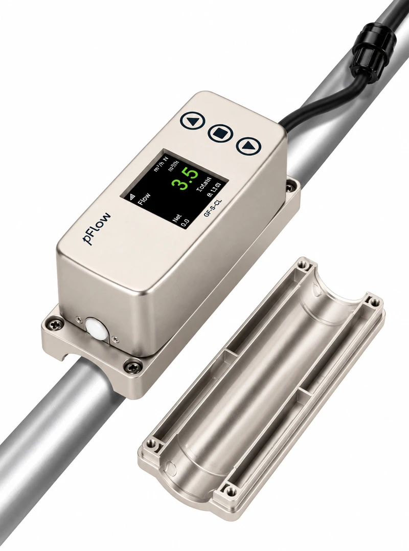
Transit-time ultrasonic measurement for small water pipes, with an integrated external clamp that installs without cutting the pipe or contacting the liquid.
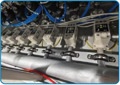
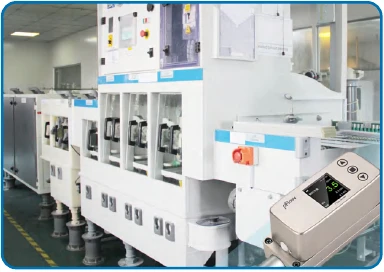
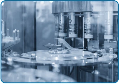
Applications include liquid cooling, cleaning, liquid-crystal manufacturing, medical equipment and laboratories. Flow data can be combined with temperature data from other sensors and devices for thermal management of heat-generating equipment.


About GF-S-CL
The all-in-one meter combines the transmitter and clamp-on transducer in a compact body. It fits stainless steel, copper, PVC and PPR pipes within the specified outside-diameter ranges.
- Quick clip-on installation without interrupting the pipeline.
- Permanent coupling pads and a reusable design for different pipe materials.
- Display shows date, flow and velocity, with colour text for clear reading in dim light.
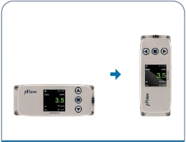
- Colour LCD with a 360° rotatable display and three touch keys.
- 4–20 mA output and RS485 communication.
- Factory configuration for the selected application industry.
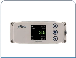
Coupling and display features
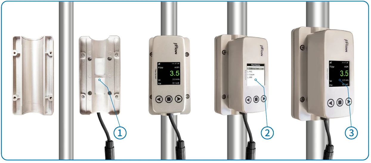
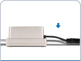
- Permanent coupling pads — lower maintenance costs.
- Reusable with different pipe materials — lower purchase costs.
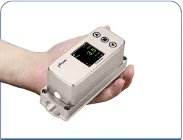
- Comprehensive display of date, flow and velocity, with colour text for clear reading in dim light.
Application and Installation Guidance
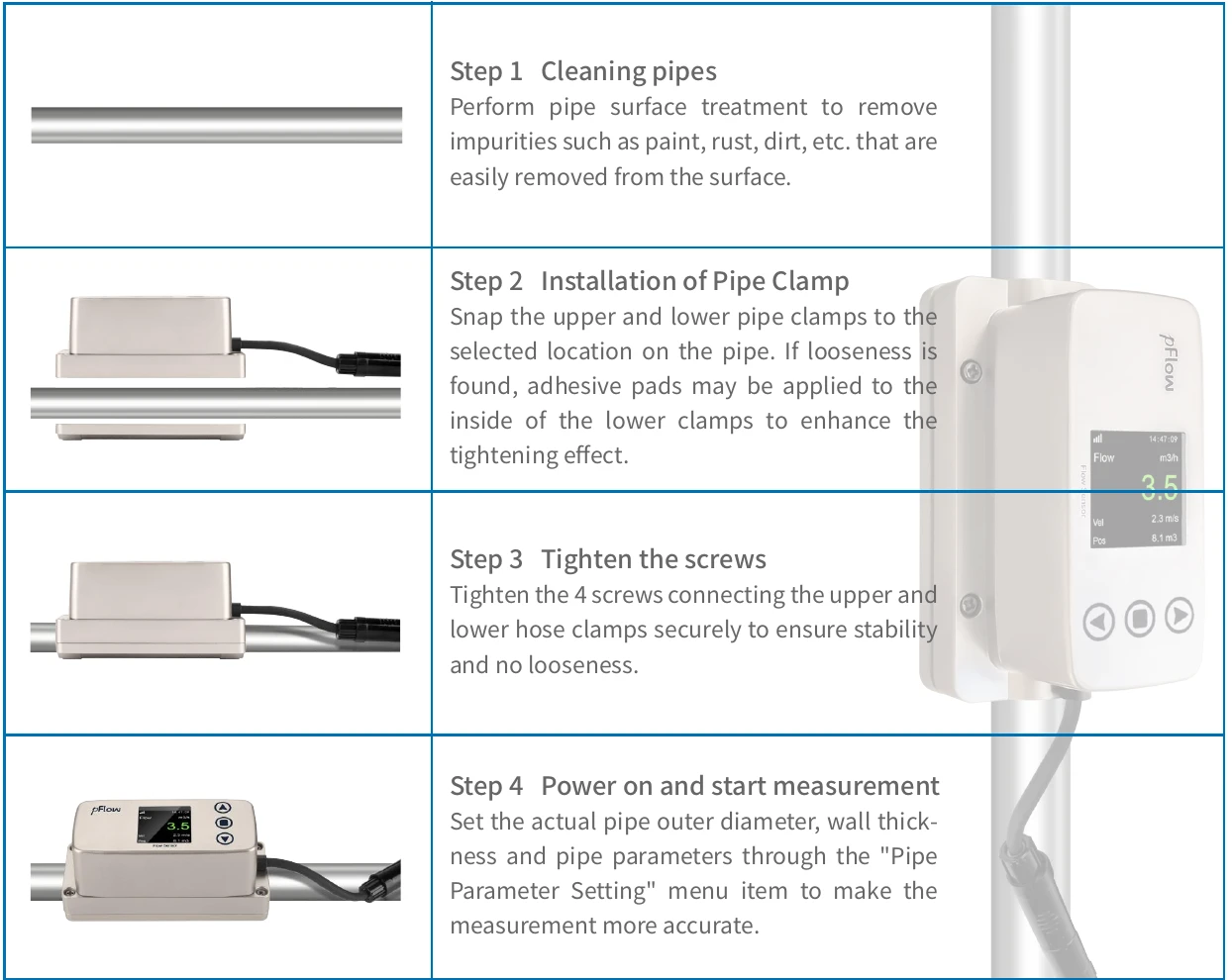
- Select a sound section of pipe and clean its outside surface.
- Apply the supplied coupling sticker to the centre of the sensor. Ensure close contact between sensor and pipe, with no air bubbles in the coupling layer.
- Align the arrow on the instrument nameplate with the liquid flow direction.
- Fit the upper and lower clamps around the pipe and tighten all four screws securely. Use the supplied rubber pads where required for a firm fit.
- Power on and set the actual pipe outside diameter, wall thickness and pipe parameters in the Pipe Parameter Setting menu.
Class B pipe fit uses the supplied adhesive pads on both sides of the clamp’s inner wall. Class B is not listed for DN15.
The specified medium is water. Accuracy can vary with pipe type, liquid and temperature; the catalogue’s standard accuracy is measured on the manufacturer’s flow standard device.
Technical Data and Wiring
- Measurement
- Transit-time ultrasonic; integrated clamp-on transmitter and transducer
- Medium
- Water
- Velocity range
- 0.03–5.0 m/s
- Accuracy
- ±3% FS at 0.3–5 m/s
- Communication
- RS485; MODBUS protocol
- Analogue output
- 4–20 mA
- Power supply
- 10–36 VDC / 500 mA
- Protection
- IP54
- Enclosure
- PC (polycarbonate)
- Pipe clamp
- PC engineering plastic
- Display
- 1.54-inch colour LCD, 240 × 240 pixels; 360° rotatable
- Controls
- 3 touch keys
- Transmitter temperature
- −10 to +50°C
- Transducer temperature
- 0–60°C
- Humidity
- 0–99% relative humidity, non-condensing
- Standard cable
- 4 m, Ø5 mm black six-core shielded cable with self-locking connectors
Six-core cable connections
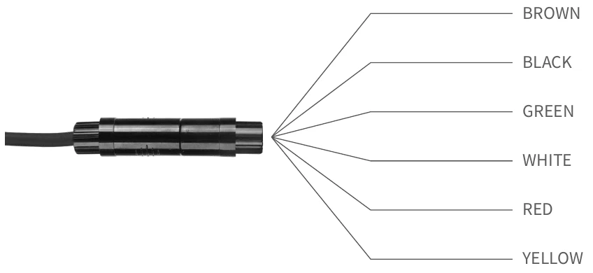
| Colour | Identifier | Function |
|---|---|---|
| Brown | + | 10–36 VDC power supply |
| Black | − | Power ground |
| Green | A | RS485+ |
| White | B | RS485− |
| Red | I+ | 4–20 mA+ |
| Yellow | I− | 4–20 mA− |
Pipe Sizes and Flow Ranges
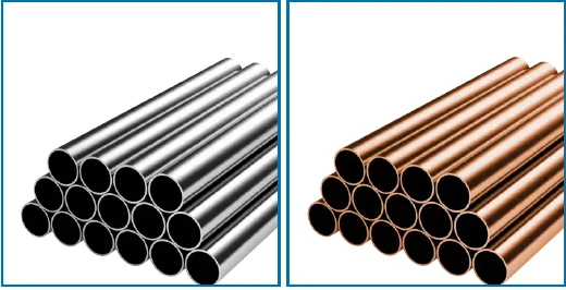
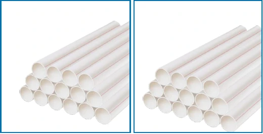
Pipe nominal inside diameter and clamp outside-diameter fit are different measurements. Check the actual pipe outside diameter against the matching class.
| Nominal size | Class A pipe OD — mm | Class B pipe OD — mm | Adapter pipe OD — mm | Flow range — m³/h |
|---|---|---|---|---|
| DN15 | 18.5–22.5 | Not listed | 18.5–22.5 | 0.2–3.5 |
| DN20 | 24–29 | 22.5–27.5 | 22.5–29 | 0.4–6 |
| DN25 | 30.5–35.5 | 29–34 | 29–35 | 0.5–9 |
| DN32 | 37.5–42.5 | 36–41 | 36–42.5 | 0.9–15 |
| DN40 | 49.5–54.5 | 48–53 | 48–54.5 | 1.3–23 |
| DN50 | 58.5–63.5 | 57–62 | 57–63.5 | 2.0–35 |
Class B fit uses the supplied rubber pads. For DN25, the adapter column gives 29–35 mm while Class A extends to 35.5 mm; confirm fit for pipe outside diameters above 35 mm.
Product Dimensions — mm
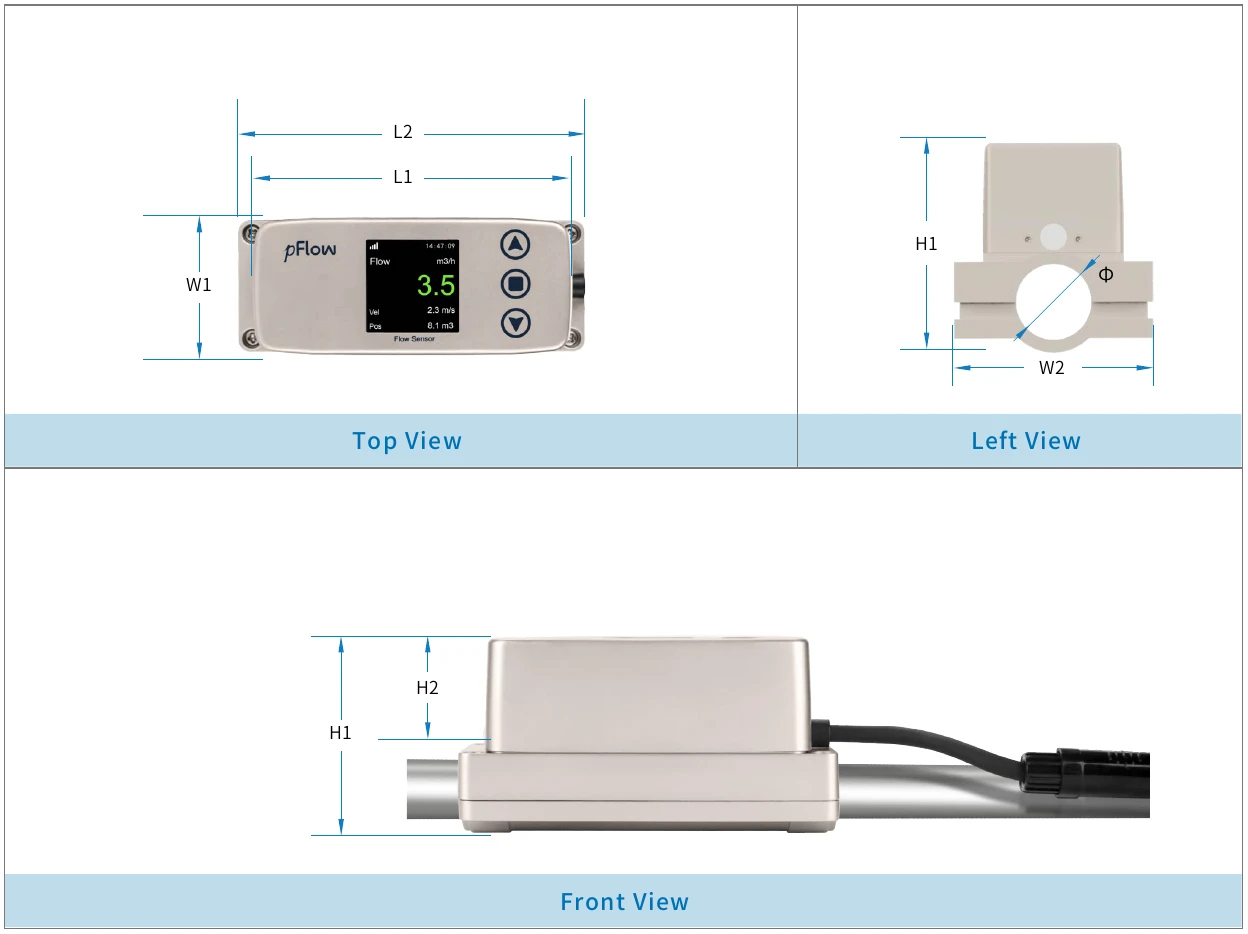
| Size | W1 | W2 | L1 | L2 | H1 | H2 | Ø |
|---|---|---|---|---|---|---|---|
| DN15 | 42 | 42 | 96 | 110 | 63 | 32.5 | 22.5 |
| DN20 | 42 | 59.5 | 96 | 110 | 69.5 | 32.5 | 29 |
| DN25 | 42 | 59.5 | 96 | 110 | 76 | 32.5 | 35.5 |
| DN32 | 42 | 64.5 | 96 | 110 | 83 | 32.5 | 42.5 |
| DN40 | 42 | 76.5 | 96 | 110 | 95 | 32.5 | 54.5 |
| DN50 | 42 | 85.5 | 96 | 110 | 104 | 32.5 | 63.5 |
Build your GF-S-CL ordering code
Example — GF-S-CL-EM-DN15
GF-S series with 4–20 mA output, energy equipment configuration and DN15 pipe size. PC engineering plastic casing and clamp; standard 4 m cable.