
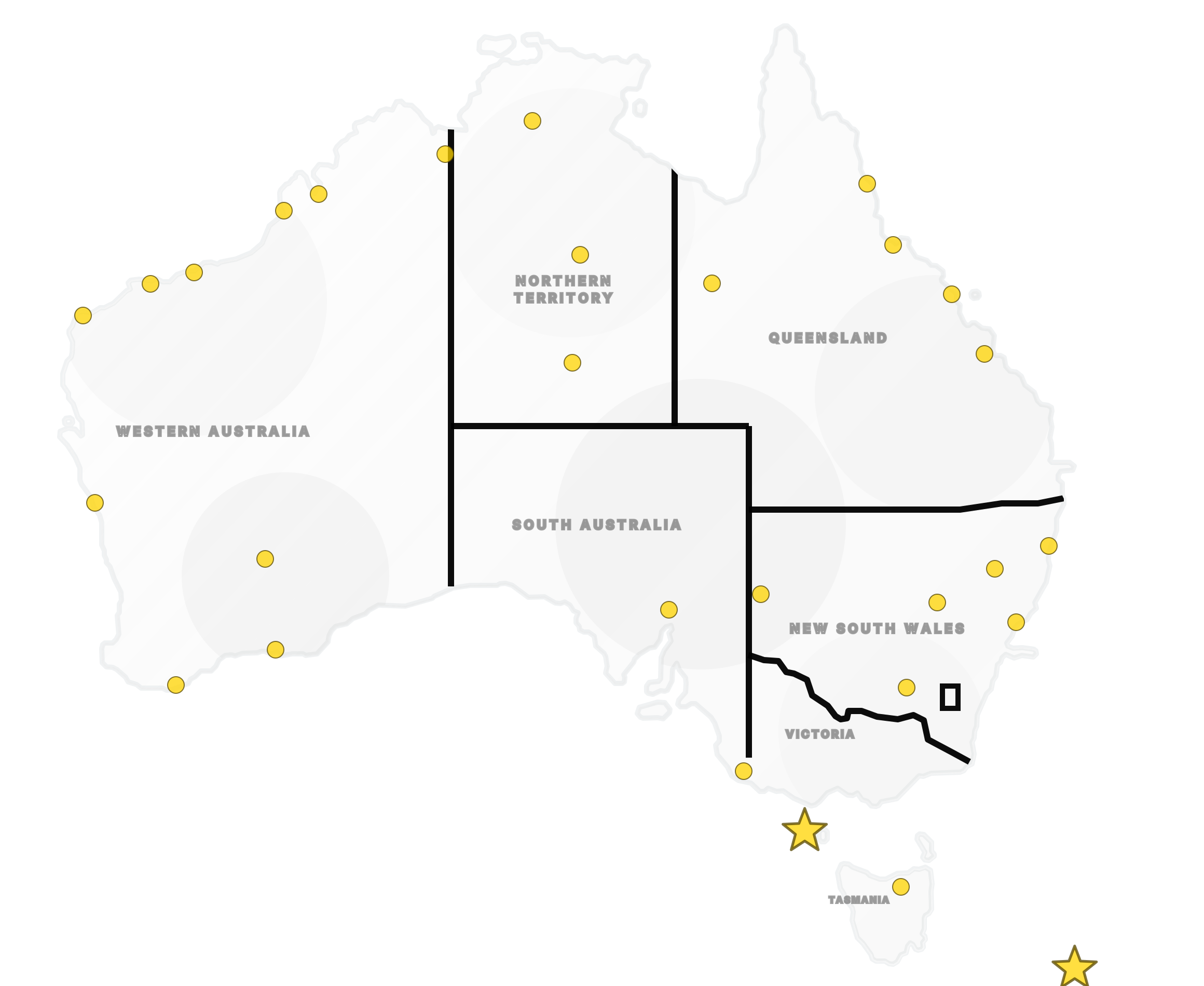
Metal Tube Flow Meter MF200
Technical Data
MF200 — For low flows of gas, liquid and steam.
- Case and body
- Painted aluminium alloy case; stainless steel body.
- Indication
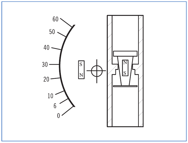
- Magnetic coupling, without seals.
- Scales calibrated
- L/h, m³/h, kg/h, %.
- Flow rates
- Water: 0.4–4,000 L/h. Air: 21–120,000 NL/h.
- Connections
- BSP, NPT; flange on request. Technical data: ¼–1½ in; ordering table also lists 2 in threads.
- Working temperature
- −40 to +180°C without electronic parts; −40 to +150°C with electronic parts.
- Working pressure
- 100 kg/cm² standard; other options on request.
- Protection class
- IP66.
- Accuracy
- ±2% F.S.; ±1.6% option. MF2001: ±6% F.S.; second scale: ±3% F.S.
- Alarm options
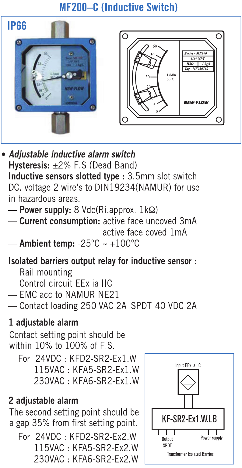
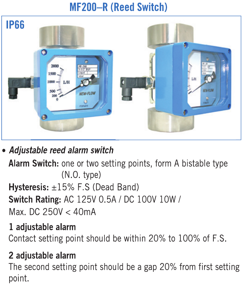
- One or two inductive or reed switches.
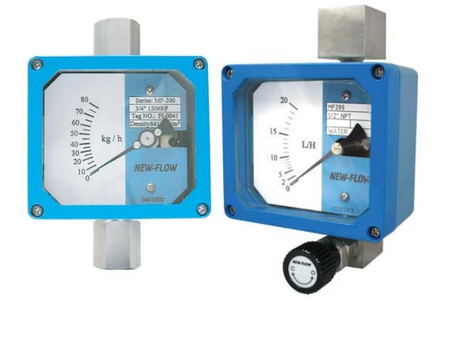

Dimensions — mm
Swipe across a drawing to see all details.
MF200-B — rear connection with needle valve
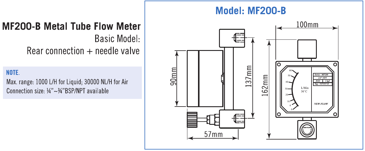
MF200-S — thread connection
MF200-R — flange connection with needle valve
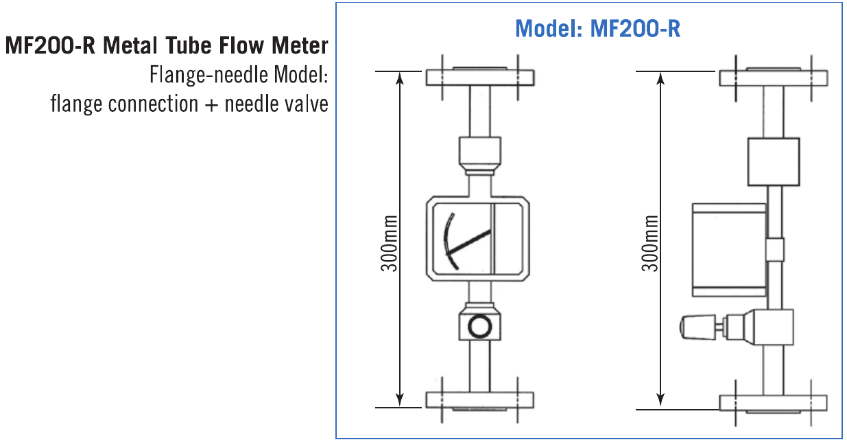
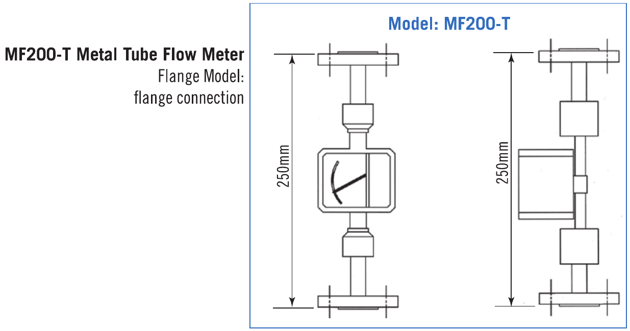
MF200-T — flange connection
Alarm options
Swipe across a drawing to see all details.
MF200-C — adjustable inductive switch and isolated barrier
MF200-R — adjustable reed switch
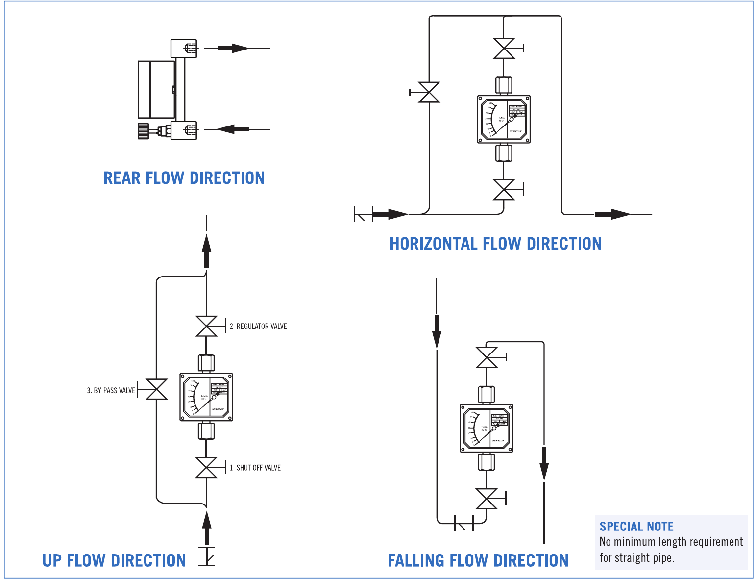
Installation and principle
Swipe across a drawing to see all details.
Rear, horizontal, up and falling flow. No minimum straight pipe length.
Magnetic indication principle
Standard Scales
| Tube | Water — L/h 20°C | Air — NL/h 0°C, 1.013 bar | Pressure loss mm water | Connection | Accuracy |
|---|---|---|---|---|---|
| MF2001 | 0.4–4 | 21–210 | 340 | ¼ in | ±6% F.S. |
| MF2002 | 0.6–6 | 33–330 | 340 | ¼ in | ±3% F.S. |
| MF2003 | 1–10 | 48–480 | 340 | ¼ in | ±2% F.S. |
| MF2004 | 1.5–15 | 60–600 | 340 | ¼ in | ±2% F.S. |
| MF2005 | 2–20 | 72–720 | 340 | ¼ in | ±2% F.S. |
| MF2006 | 3–30 | 90–900 | 340 | ¼ in | ±2% F.S. |
| MF2007 | 5–50 | 120–1200 | 340 | ¼ in | ±2% F.S. |
| MF2008 | 6–60 | 180–1800 | 340 | ¼ in | ±2% F.S. |
| MF2009 | 10–100 | 300–3000 | 340 | ¼ in | ±2% F.S. |
| MF2010 | 15–150 | 500–5000 | 340 | ½ in | ±2% F.S. |
| MF2011 | 25–250 | 750–7500 | 340 | ½ in | ±2% F.S. |
| MF2012 | 45–450 | 1500–15000 | 340 | ½ in | ±2% F.S. |
| MF2013 | 75–750 | 2000–20000 | 340 | ¾ in | ±2% F.S. |
| MF2014 | 100–1000 | 3000–30000 | 340 | 1 in | ±2% F.S. |
| MF2015 | 150–1500 | 5000–50000 | 450 | 1½ in | ±2% F.S. |
| MF2016 | 200–2000 | 7500–75000 | 450 | 1½ in | ±2% F.S. |
| MF2017 | 300–3000 | 9000–90000 | 450 | 1½ in | ±2% F.S. |
| MF2018 | 350–3500 | 11000–110000 | 450 | 1½ in | ±2% F.S. |
| MF2019 | 400–4000 | 12000–120000 | 450 | 1½ in | ±2% F.S. |
Water at 20°C; air at 0°C and 1.013 bar. Rear connection B: maximum 1,000 L/h water or 30,000 NL/h air; ¼–¾ in BSP/NPT. No standard scale is published for the 2 in thread ordering option. Custom ranges require review. Technical data are subject to change.
Build your MF200 ordering code
Select the options in the same order as the PDF. Each choice shows its ordering code.