

Model I Flange Sight Glass
Corrosion-resistant wetted insert · ANSI B16.5 flange connection
About Model I
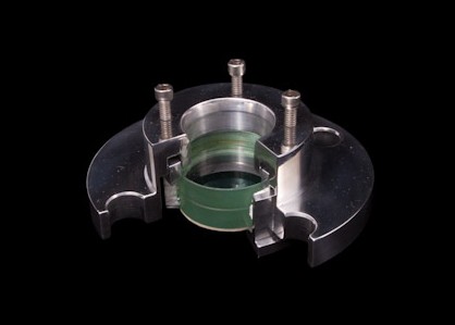
The Model I Flange unit mounts on standard ANSI B16.5 (2" to 24") flange accommodations and is designed for applications where corrosion resistance is needed only on wetted parts. The insert (wetted part) of the Model I may be made of stainless steel, glass-lined, or Hastelloy, etc. while the flange housing (non-wetted) can be made of carbon steel. Units can be manufactured to meet your pressure and temperature requirements, and different materials of construction are available to meet your process needs. Applications requiring DIN standards or non-ANSI flanges are available upon request.
- Connection
- ANSI B16.5 flange
- Product size range
- 2–24 inches; dimensions below cover 2–8 inches
- Standard lens
- Two-piece laminated tempered soda lime
- Other Model I connection
- Model I Weld sight glass
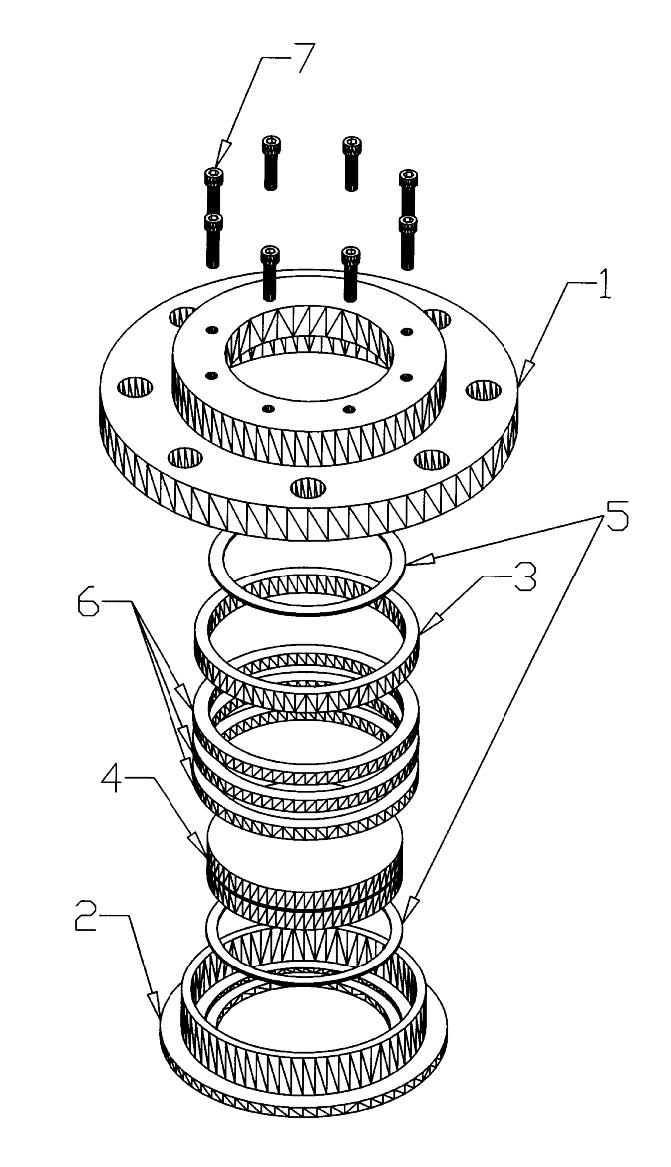
Construction and material options
- 1Flange
- Carbon Steel SA-105 (Standard); 316 Stainless Steel SA-182; 304 Stainless Steel SA-182
- 2Insert (wetted part)
- 316 Stainless Steel SA-351; 304 Stainless Steel SA-351; Carbon Steel SA-519; Glass-lined; Hastelloy; Inconel; Titanium; Monel; Alloy 20; other materials on request
- 3Compression ring
- 304 Stainless Steel SA-351; Carbon Steel SA-519
- 4Lens
- Two-Piece Laminated Tempered Soda Lime (Standard); Tempered Borosilicate; Annealed Borosilicate; Quartz; Lexan; Acrylic; Mica shields
- 5Lens cushion gaskets
- Teflon®; Grafoil®; Gylon®; Blue-Gard®; other materials on request
- 6Lens packing
- Combination Teflon® Impregnated and Viton® (Standard); Graphite; FDA Teflon®; other materials on request
- 7Compression screws
- 18-8 Stainless Steel; Carbon Steel SA-193
Engineering dimensions — inches
Use the drawing letters with the table below. Size and rating are shown as inches–psi, as shown in the engineering sheet.
For other sizes, DIN or non-ANSI flange connections, select a custom requirement in the options below.
Open the original engineering sheet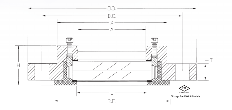
| Size–psi | O.D. | A | T | R.F. | J | H | X | Bolt holes — qty | Bolt hole dia. | Bolt circle dia. |
|---|---|---|---|---|---|---|---|---|---|---|
| 2–150 | 6 | 1 3/4 | 11/16 | 3 5/8 | 1 15/16 | 2 1/16 | 3 1/2 | 4 | 3/4 | 4 3/4 |
| 2–300 | 6 1/2 | 1 3/4 | 13/16 | 3 5/8 | 1 15/16 | 2 1/16 | 3 5/8 | 8 | 3/4 | 5 |
| 2–600 | 6 1/2 | 1 3/4 | 1 | 3 5/8 | 1 15/16 | 2 1/16 | 3 5/8 | 8 | 3/4 | 5 |
| 3–150 | 7 1/2 | 2 5/8 | 7/8 | 5 | 2 7/8 | 2 1/16 | 4 5/8 | 4 | 3/4 | 6 |
| 3–300 | 8 1/4 | 2 5/8 | 1 1/16 | 5 | 2 7/8 | 2 1/16 | 4 5/8 | 8 | 7/8 | 6 5/8 |
| 3–600 | 8 1/4 | 2 5/8 | 1 1/4 | 5 | 2 7/8 | 2 5/16 | 4 7/8 | 8 | 7/8 | 6 5/8 |
| 4–150 | 9 | 3 5/8 | 7/8 | 6 3/16 | 3 3/4 | 2 1/16 | 5 7/8 | 8 | 3/4 | 7 1/2 |
| 4–300 | 10 | 3 5/8 | 1 3/16 | 6 3/16 | 3 3/4 | 2 5/16 | 6 | 8 | 7/8 | 7 7/8 |
| 4–600 | 10 3/4 | 3 5/8 | 1 1/2 | 6 3/16 | 3 3/4 | 3 1/16 | 6 1/4 | 8 | 1 | 8 1/2 |
| 6–150 | 11 | 5 1/2 | 15/16 | 8 1/2 | 5 3/4 | 2 9/16 | 8 | 8 | 7/8 | 9 1/2 |
| 6–300 | 12 1/2 | 5 1/2 | 1 3/8 | 8 1/2 | 5 3/4 | 3 1/16 | 8 3/8 | 12 | 7/8 | 10 5/8 |
| 6–600 | 14 | 5 1/2 | 1 7/8 | 8 1/2 | 5 3/4 | 3 9/16 | 8 5/8 | 12 | 1 1/8 | 11 1/2 |
| 8–150 | 13 1/2 | 7 3/8 | 1 1/16 | 10 5/8 | 7 11/16 | 3 1/16 | 10 1/4 | 8 | 7/8 | 11 3/4 |
| 8–300 | 15 | 7 3/8 | 1 9/16 | 10 5/8 | 7 11/16 | 3 5/16 | 10 1/2 | 12 | 1 | 13 |
FM approval excludes 600 psi models.
Approvals and documentation
The original product documentation states:
This sight glass has been certified as maintaining a Quality Assurance System in accordance with the Pressure Equipment Directive 97/23/EC (PED) Annex I, Paragraph 4.3 by the Certification Body 0036 of the TÜV Industrie Service GmbH.
FM approval excludes 600 psi models.


Configure your Model I flange
Select a size and rating, or describe a custom connection. Material choices can be left for Sightflow to advise.