
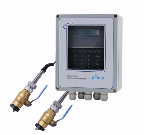
D348D Ultrasonic Flowmeter
Multipath Ultrasonic Flowmeter
Applications and measurement
Water supply, circulation cooling water, sewage treatment and power-plant circulation water. Published examples include DN800 water supply and DN1000 cooling-water installations.
Multipath ultrasonic measurement for industrial and commercial applications, with insertion and spool-piece configurations. PICOFly time measurement reaches 10 picoseconds (0.01 nanosecond) resolution and a sampling rate up to 1000 times per second. Published spool-piece accuracy is ±0.2% and insertion accuracy ±0.5% of measured value.
About D348D
The D348D adopts Gentos PICOFly time measurement technology for high-response, high-accuracy ultrasonic measurement.
- Low power consumption, high reliability, anti-jamming and broad applicability.
- Clear, user-friendly menu selections.
- Daily, monthly and yearly totalized flow.
- Positive, negative and net totalizers with scale factor (span) and 7-digit display; totalizer pulse and frequency outputs transmitted through relay and open collector.
Application and Installation Guidance
Measurement location
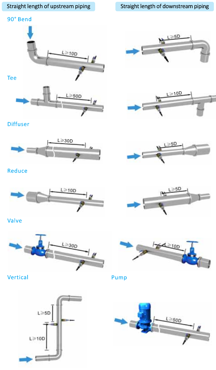
Select a measurement site where the fluid flow profile is fully developed for highly accurate measurement.
Choose a pipe section that is always full of liquid, such as a vertical pipe with upward flow or a full horizontal pipe.
Provide at least the straight upstream and downstream lengths shown for the transducer installation.
Ensure the pipe surface temperature at the measuring point is within the transducer temperature limits.
Check the pipe interior carefully; where possible, choose a section free of excessive corrosion or scaling.
Channels and transducers
Published sensor choices: 2 channels for pipe sizes over DN150; 3 over DN300; 4 over DN400; and 6 over DN600.
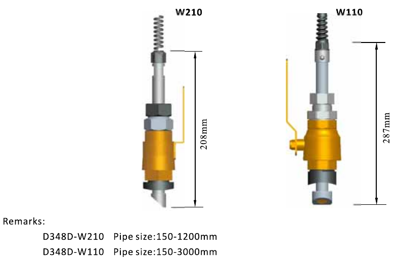
W210 and W110 are wetted transducers, rated −40°C to +80°C. The dimension notes specify W210 for 150–1200 mm pipe and W110 for 150–3000 mm. Review these limits alongside the installation drawings.
Spool pieces
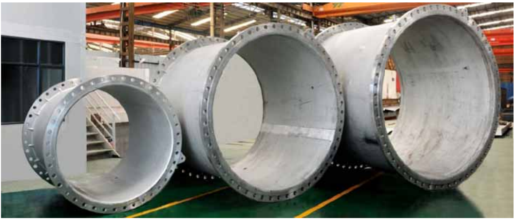
Carbon-steel spool and flange dimensions are shown below. DIN, JIS, EN and other pipe/flange standards are available with the customer's operating standard and drawing; pricing is revised accordingly. Large pipes and flanges also require the operating standard and drawing.
Include spool-piece requirements in your enquiry; the published ordering table does not define a separate spool-piece code.
Technical Data, Dimensions and Wiring
Performance specifications
- Flow range
- 0.01–7 m/s (0.03–23 ft/s)
- Accuracy
- Spool piece: ±0.2% of measured value. Insertion: ±0.5% of measured value.
- Repeatability
- Spool piece: 0.07%. Insertion: 0.15%.
- Pipe size
- Spool piece: 100–3000 mm (4–120 in). Insertion: 100–5000 mm (4–200 in).
Function specifications
- Analog output
- 4–20 mA; maximum load 750 Ω.
- Pulse output
- 0–10 kHz, OCT.
- Relay output
- 125 VAC at 1 A or 30 VDC at 2 A.
- Communication
- RS232 / RS485; Modbus Protocol.
- Power supply
- 90–245 VAC, 48–63 Hz or 12–36 VDC.
- Keypad
- 22 keys with tactile action: 16 (4 × 4) touch keys and 6 function keys.
- Display
- 40 characters, 2 lines (20 × 2), alphanumeric backlit LCD.
- Temperature
- Transmitter: −10°C to 60°C (14°F to 140°F). Transducer: −40°C to 80°C (−40°F to 176°F).
- Humidity
- Up to 99% RH, non-condensing.
- Installation
- Wall mount.
Physical specifications
- Transmitter
- IP65. Hazardous rating printed in specifications: ExiaIIBT4.
- Transducer
- IP68; sealing design.
- Transducer cable
- Standard: 30 ft (9 m). Maximum: 344 ft (105 m).
- W210
- 208 mm dimension; pipe size 150–1200 mm.
- W110
- 287 mm dimension; pipe size 150–3000 mm.
- Transmitter dimensions
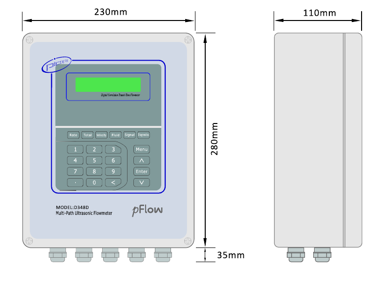
- 230 × 280 × 110 mm; 35 mm cable-gland extension.
Configuration notes
- Ordering output label
- The ordering table prints RS-458; the specification and wiring diagram identify RS485.
- Pipe-size limits
- The general insertion range is 100–5000 mm; the transducer drawing specifies W210 at 150–1200 mm and W110 at 150–3000 mm. Confirm the selected transducer and installation for the pipe.
- Flow range in ordering table
- The ordering table prints 0.03–±23 ft/s (0.01–±7 m/s). It also lists ±0.5% accuracy at ±1.6 to ±16 ft/s.
- Power supply labels
- The wiring artwork labels DC 10–36 V; the specification and ordering table list 12–36 VDC.
- Hazardous-area markings
- The specification prints ExiaIIBT4; enclosure option 2 is labelled Exd II BT4 in the ordering table. Confirm the required classification.
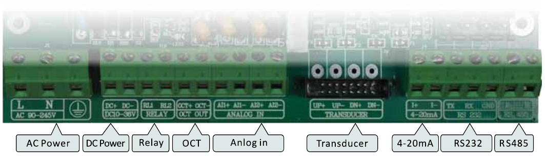
Wiring Diagram
Transmitter Dimensions — mm
Transducer Dimensions — mm
Flange Dimensions
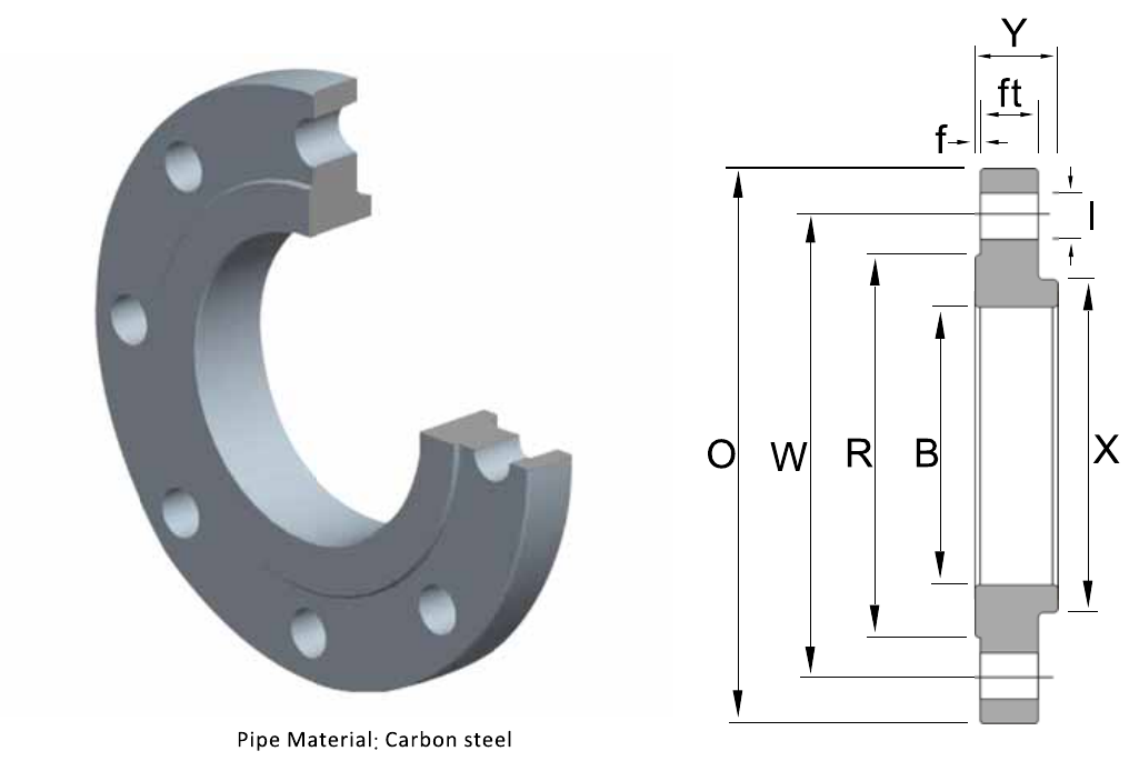
| NPS | DN | Overall Ø O | Bolt circle Ø W | Bolt hole Ø I | Holes n | Face Ø R | Raised face f | Thickness ft | Threaded / slip-on / socket welding Y | Hub Ø X | Inside Ø B |
|---|---|---|---|---|---|---|---|---|---|---|---|
| 4 | DN100 | 230 | 190.5 | 19.1 | 8 | 157.2 | 2 | 23.9 | 32 | 135 | 116.1 |
| 5 | DN125 | 255 | 215.9 | 22.3 | 8 | 185.7 | 2 | 23.9 | 35 | 164 | 143.8 |
| 6 | DN150 | 280 | 241.3 | 22.3 | 8 | 215.9 | 2 | 25.4 | 38 | 192 | 170.7 |
| 8 | DN200 | 345 | 298.5 | 22.3 | 8 | 269.9 | 2 | 28.6 | 43 | 246 | 221.5 |
| 10 | DN250 | 405 | 362.0 | 25.4 | 12 | 323.8 | 2 | 30.2 | 48 | 305 | 276.2 |
| 12 | DN300 | 485 | 431.8 | 25.4 | 12 | 381.0 | 2 | 31.8 | 54 | 365 | 327.0 |
| 14 | DN350 | 535 | 476.3 | 28.6 | 12 | 412.8 | 2 | 35.0 | 56 | 400 | 359.2 |
| 16 | DN400 | 595 | 539.8 | 28.6 | 16 | 469.9 | 2 | 36.6 | 62 | 457 | 410.5 |
| 18 | DN450 | 635 | 577.9 | 31.8 | 16 | 533.4 | 2 | 39.7 | 67 | 505 | 461.8 |
| 20 | DN500 | 700 | 635.0 | 31.8 | 20 | 584.2 | 2 | 42.9 | 71 | 559 | 513.1 |
| 24 | DN600 | 815 | 749.3 | 35.0 | 20 | 692.2 | 2 | 47.7 | 81 | 663 | 616.0 |
ASME B16.5-2009: page 64, Chart 4 — flange processing surface dimensions; page 71, Chart 7 — 150 Grade flange drillplate; page 73, Chart 8 — 150 Grade flange dimensions.
Spool Piece Dimensions
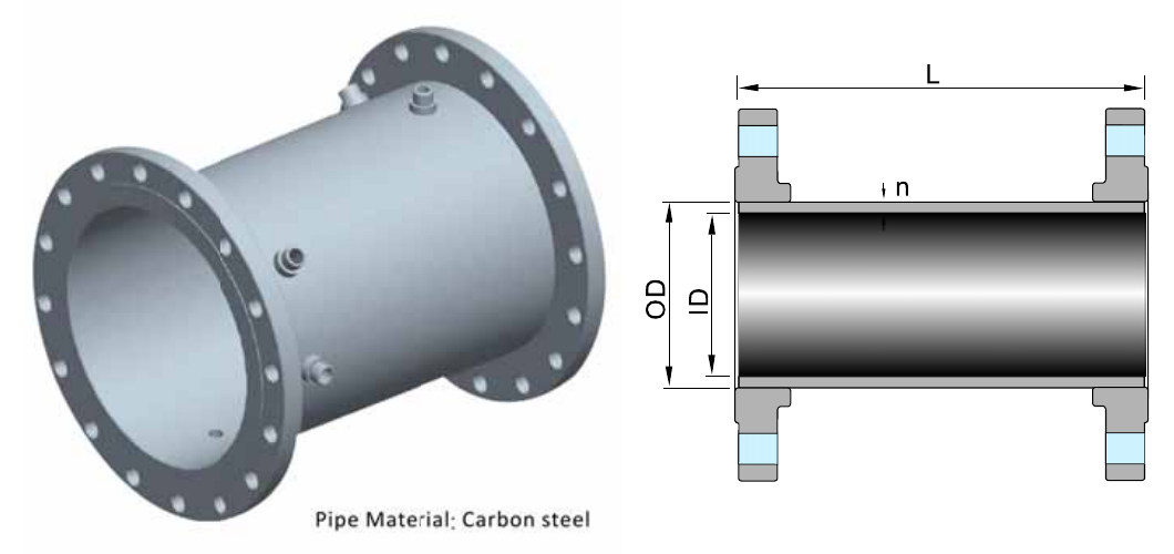
| NPS | DN | Length L | Outer Ø OD | Inner Ø ID | Thickness n | Flange weight (kg) | Spool piece weight (kg) |
|---|---|---|---|---|---|---|---|
| 4 | DN100 | 400 | 114.30 | 102.26 | 6.02 | 5.7 | 18.8 |
| 5 | DN125 | 420 | 141.30 | 128.20 | 6.55 | 6.5 | 22.7 |
| 6 | DN150 | 450 | 168.30 | 154.08 | 7.11 | 7.7 | 29.0 |
| 8 | DN200 | 510 | 219.10 | 202.74 | 8.18 | 12.2 | 46.5 |
| 10 | DN250 | 580 | 273.00 | 254.46 | 9.27 | 16.2 | 66.5 |
| 12 | DN300 | 640 | 323.80 | 304.74 | 9.53 | 25.0 | 97.2 |
| 14 | DN350 | 680 | 355.60 | 336.54 | 9.53 | 33.7 | 122.5 |
| 16 | DN400 | 740 | 406.40 | 387.34 | 9.53 | 41.6 | 151.8 |
| 18 | DN450 | 780 | 457.00 | 437.94 | 9.53 | 46.2 | 173.9 |
| 20 | DN500 | 860 | 508.00 | 488.94 | 9.53 | 59.5 | 219.9 |
| 24 | DN600 | 980 | 610.00 | 590.94 | 9.53 | 83.2 | 303.4 |
ASME B36.10M-2004, page 5, Chart 1 — welded and rolled seamless steel tube dimensions and weight. For other standards or large pipes/flanges, provide the operating standard and drawing.
Transducer Installation Methods
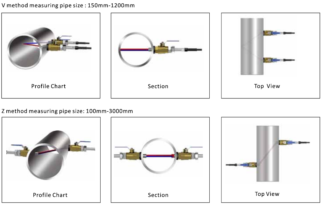
Installation Site Selection
Minimum straight pipe lengths, expressed as multiples of pipe diameter D:
- 90° bend
- 10D upstream / 5D downstream
- Tee
- 50D / 10D
- Diffuser
- 30D / 5D
- Reducer
- 10D / 5D
- Valve
- 30D / 10D
- Vertical pipe
- 10D / 5D
- Pump
- 50D after the pump
Spool Piece Production and Testing
Production
The manufacturer describes a 3000 m² pipeline processing plant covering stainless-steel plate cutting, reelpiping, welding, flange mating, polishing and pickling. Non-destructive testing is carried out throughout welding, with a material testing report to meet design requirements.
Third-party testing
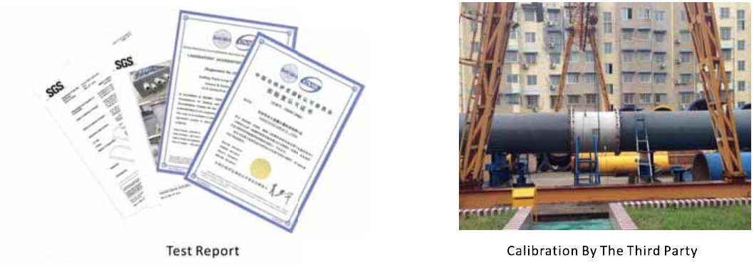
Products can be tested by a third party according to customer requirements.
Build your D348D ordering code
Example — Standard Model: D348D-1-1-2-W210-030
Multipath ultrasonic flowmeter, 4–20mA output, two-channel path wetted transducer with 9m cable.