

TMFC Mass Flow Controller
Flow Rate & Totalizer LCD Display — Flow Rate With or Without LCD Display.
TMFC SERIES
Flow Rate & Totalizer LCD DisplayFlow Rate With or Without LCD Display
- ±1% Accuracy
- Linear Output
- Thermal Technology
- For Using in Non Corrosive Gas
- For Flow Rates up to 200 SLM
- Power Supply Included
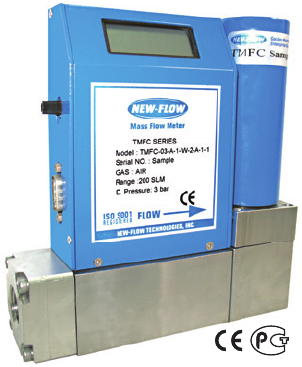
The NEW-FLOW Thermomal Mass Flow Meters provide high performance. Thermal Technology offers advantages in accuracy, sensitivity and turn quality components and the latest technology are combined to provide reliable, compact meters and controllers. The TMFC Series comes With or Without an LCD Display; or Flow Rate with Totalizer LCD Display. All models come with linear 0-5VDC and 4-20mA output. The TMFC Series measures the mass flow rate of gases in 3 ranges from 0-100 SLM to 0-200 SLM as shown in the range table. The TMFC Series combines a mass flow transducer with an electromagnetic proportional valve. Valves are not recommended as shut off valves. Controllers use a 0-5VDC linear set-point signal supplied from the local set-point pot or from a remote source.
Technical Data and Dimensions
- Type
- Without LCD Display; Flow Rate with LCD Display; Flow Rate with LCD Display & Blue Back Lighted; Flow Rate with Totalizer LCD Display & Blue Back Lighted
- Wetted Parts Material
- Standard flowbody—SS316, option available. O-ring–Viton
- Output Signal
- 0-5 VDC Linear min. load 1000 Ω or 4-20 mA Linear, loop resistance 500 Ω
- Input Power
- 24VDC standard
- Accuracy
- ±1% F.S. (including linearity)
- Turn Down Ratio
- 100:1
- Repeatability
- ±0.15% F.S. or Better
- Electric Connection
- 9 Pin Sub “D”
- Process Connection
- ½” NPT female
- Control Signal
- Integral or 0-5 VDC
- Control Valve
- Electromagnetic N/C (Norm. Closed)
- Range
- 0-100 SLM to 0-200 SLM
- Max. Pressure
- 500 PSIG
- Temperature Range
- 0–50°C
- Response Time
- 1 Second
- Temp. Coefficient
- 0.05% Full Scale per 1°C or Better
- Pressure Coefficient
- 0.01% Full Scale per PSIG or Better
- Flow Unit
- Kg, GAL, Nℓ, Nm³, cc, ℓ, M³ (Flow rate with LCD display: Label by manufacturer; Flow rate with totalizer LCD display: Unit LCD display)
- Weight
- app. 3.27 kg with power supply; app. 3.41 kg with power supply & totalizer
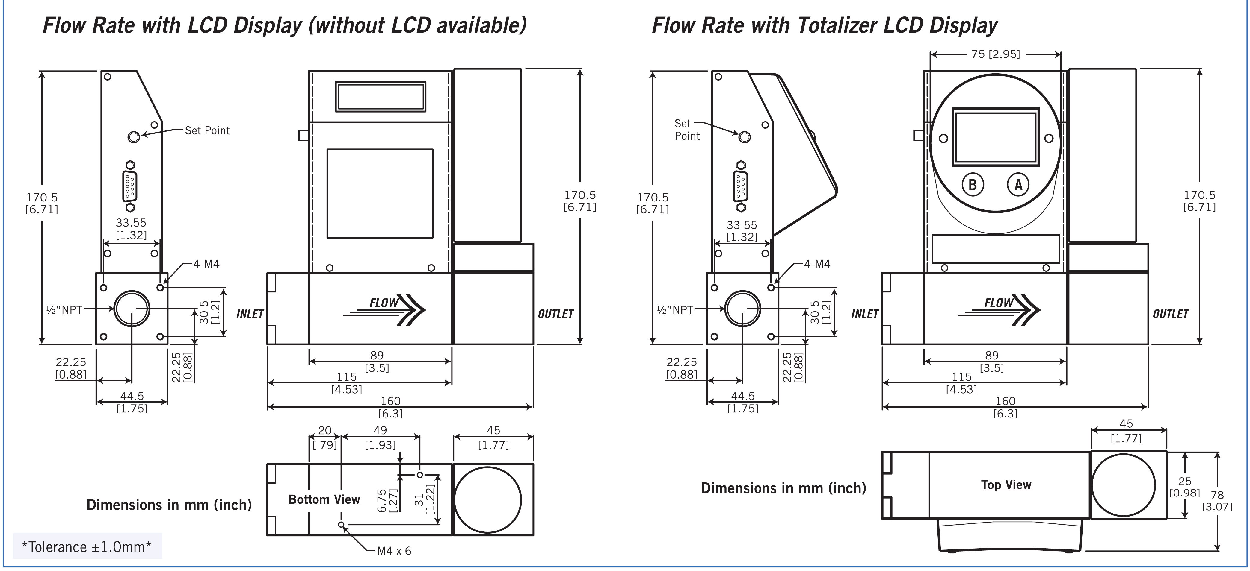
Dimensions — mm (in)
Display and decimal point functions
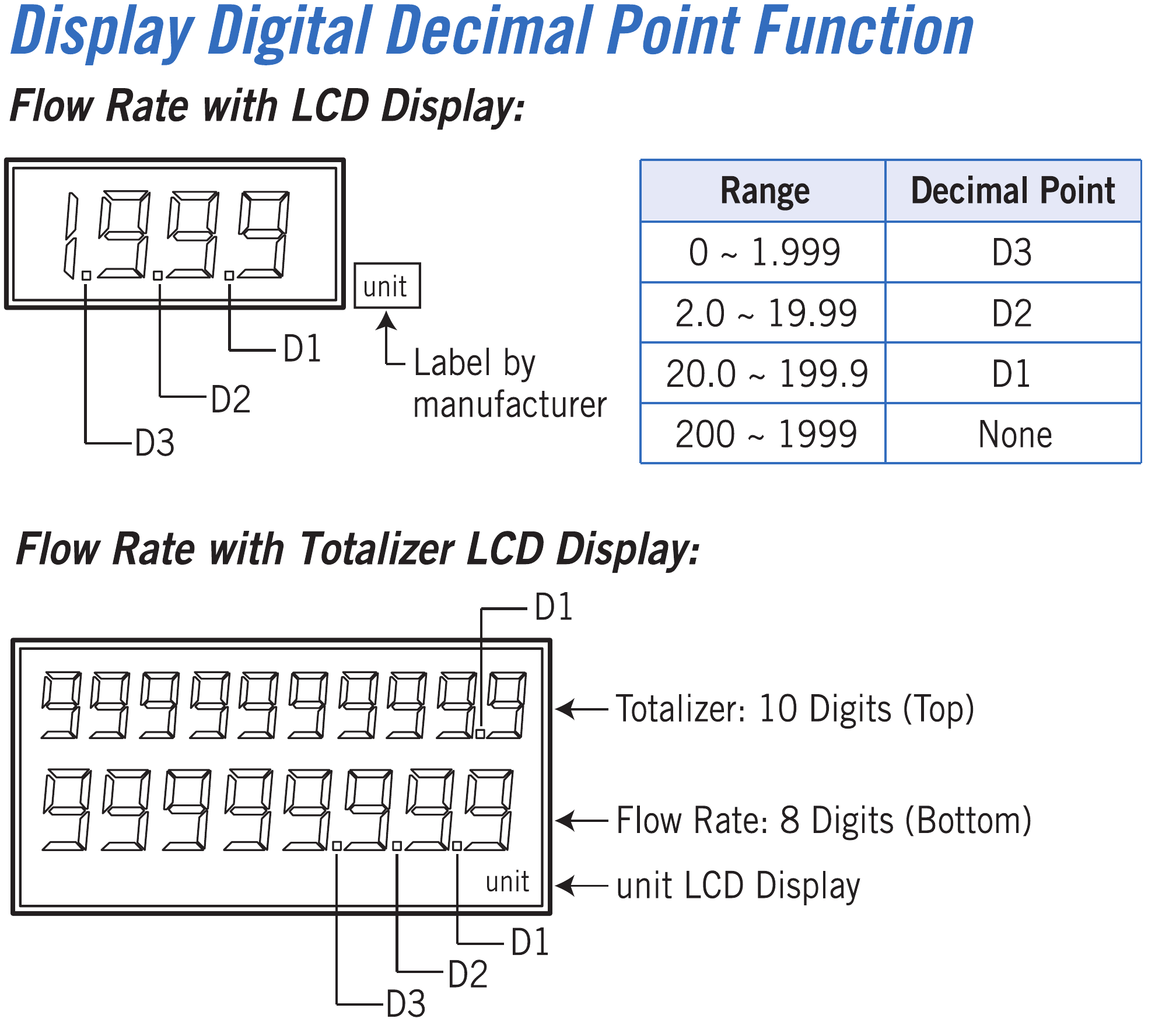
Flow-rate LCD
The flow unit is labelled by the manufacturer. Decimal-point positions depend on the displayed range:
| Range | Decimal point |
|---|---|
| 0–1.999 | D3 |
| 2.0–19.99 | D2 |
| 20.0–199.9 | D1 |
| 200–1999 | None |
Flow-rate and totalizer LCD
The upper row shows the accumulated total with 10 digits; the lower row shows flow rate with 8 digits. The flow unit appears on the LCD. The diagram identifies the D1, D2 and D3 decimal-point positions.
Display choices are no LCD, flow-rate LCD, flow-rate LCD with blue backlight, or flow-rate and totalizer LCD with blue backlight.
Dimension drawings include both display versions, all side, front and mounting views, millimetres and inches, and the ±1.0 mm tolerance.
Specify the actual gas and operating conditions for calibration review.
Standard Scales and Operating Differential Pressure
Standard Scales
| Code | Flow range |
|---|---|
| 00 | 0–100 SLM |
| 01 | 0–150 SLM |
| 02 | 0–200 SLM |
03 — Custom flow range
Connection: ½ in NPT female. Custom flow range: maximum 200 SLM.
Operating differential pressure
- 100 SLM < F.S. < 200 SLM: 2–3 kg/cm².
Low differential pressure depends on the gas and flow rate.
Build your TMFC ordering code
Choose each option in PDF order. Single available options are selected automatically.