
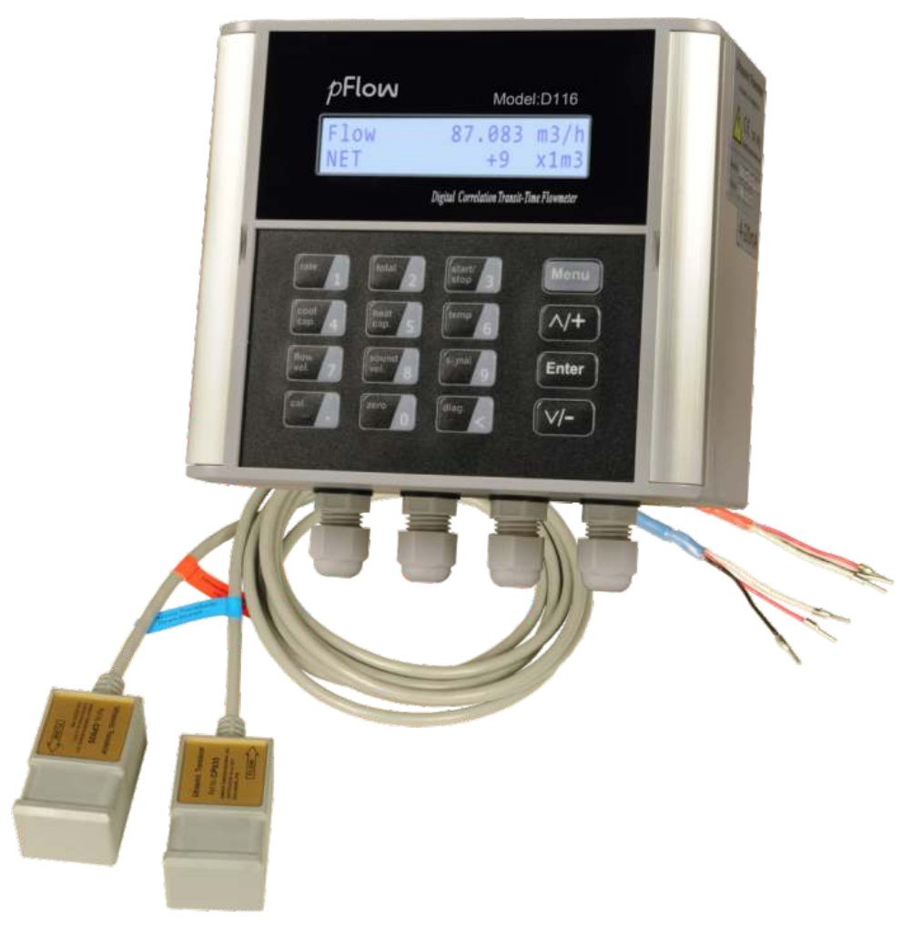
D116 Ultrasonic Flowmeter
Digital Correlation Transit Time Flowmeter
Applications and measurement
Hot, cooling and potable water; industrial water treatment; mining processes; water fire-suppression testing; pipeline leak detection and inspection; and flow surveys.
The wall-mounted meter uses external clamp-on transducers, so installation requires no pipe cutting or process shutdown. Transit-time measurement compares upstream and downstream sound travel times between a pair of transmitting and receiving transducers to calculate flow.
About D116
D116 Series Ultrasonic Flowmeter is a state-of-the-art iniversal transit-time flowmeter designed using FPGA chip and low-voltage broadband pulse transmission.
Comparing with other traditional flowmeter or ultrasonic flowmeter, it has distinctive features such as high precision, high reliability, high capability and low cost, the flowmeter features other advantages:
- TVT technology designed.
- Less hardware components, low voltage broadband pulse transmission, low consumption power.
- Clear, user-friendly menu selections make flowmeter simple and convenient to use.
- Daily, monthly and yearly totalized flow
- Parallel operation of positive, negative and net flow totalizes with scale factor (span) and 7 digit display, while the output of totalize pulse and frequency output are transmitted via relay and open collector.
Application and Installation Guidance
D116 HD reference guidance
Pipe and liquid suitability
Preconfigured pipe materials: carbon steel, stainless steel, PVC and copper. Lined pipes are not supported. Consider D118 for other pipe materials, lined pipes or other liquids.
Use clean water with few or no particles or entrained air bubbles. Seawater may work because its sound speed is similar to water, but accuracy may be reduced: the meter calculates using water’s sound speed. Excessive suspended solids prevent operation; approximately 5% is a guide, with the limit varying by application.
Measurement location
Choose a fully developed, stable, laminar flow profile and avoid turbulence. The pipe must remain full because the signal cannot travel through air. Suitable locations include upward-flowing vertical pipes and full horizontal pipes.
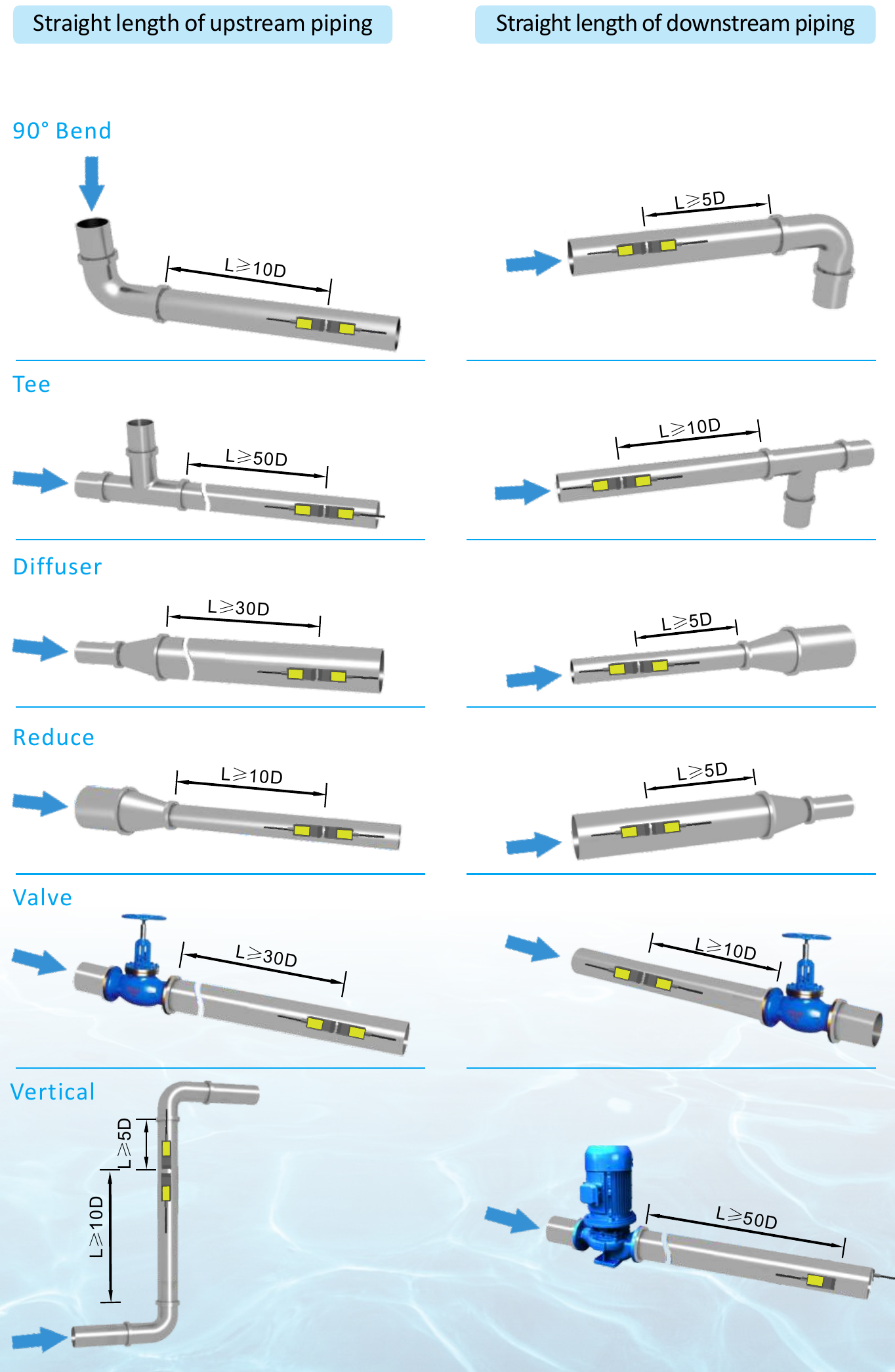
On horizontal pipes, mount transducers on the sides to avoid air or gas at the top and sediment at the bottom. A general guide is 10 pipe diameters upstream and 5 downstream; requirements vary with the installation. Refer to Installation Site Selection below.
Setup and mounting
Enter the pipe outside diameter, wall thickness and material into the meter to obtain the required transducer spacing. Apply couplant grease generously to the sensing faces and mount the transducers at that spacing.
The reference kit includes couplant and metal straps for pipes up to approximately 300 mm outside diameter. For larger pipes, ratchet straps are an optional, extra-cost mounting method.
Response time and limitations
Allow at least a few seconds for the signal to stabilise and show accurate readings. Intermittent flow, such as a pump running for 20 seconds then stopping, or diaphragm-pump flow, is not ideal.
Damping is enabled by default to average and stabilise the display. The reference recommends 3–10 seconds; setting it to zero gives a faster response to flow changes.
Accurate low dosing and custody-transfer applications are unsuitable: some totalised flow can be missed while the signal attenuates and the measurement ramps up, depending on damping.
Technical Data, Dimensions and Wiring
Performance specifications
- Flow range
- ±0.03ft/s ~ ±16ft/s (±0.01m/s ~ ±5m/s)
- Accuracy
- ±1.0% of measured value
- Repeatability
- 0.3%
- Pipe size
- Clamp-on: 1" ~ 48" (25mm ~ 1200mm)
- Fluid
- Water.
- Pipe material
- Carbon steel, stainless steel, PVC.
Function specifications
- Outputs
- Specification table: OCT pulse 0 ~ 5000Hz; analog 4 ~ 20mA, max load 750Ω. Ordering table: OCT pulse 0-10KHz, Relay output, 4-20mA optional.
- Communication interface
- Specification table: RS485 MODBUS. Ordering table: RS232, Modbus Protocol; RS232 or RS485 by selected output mode.
- Power supply
- 10 ~ 36VDC, 1A max.
- Keypad
- 16 (4×4) key with tactile action
- Display
- 20×2 lattice alphanumeric, back lit LCD.
- Temperature
- Specification table — Transmitter: 14°F ~ 122°F (-10°C ~ 50°C). Transducer: 32°F ~ 176°F (0°C ~ 80°C). Ordering table: -20°C ~ 50°C; also lists -40°F ~ +140°F (-40°C ~ 60°C) without identifying the component.
- Humidity
- Up to 99% RH, non-condensing
Physical specifications
- Installation method
- wall mount
- Transmitter
- PC/ABS, IP65.
- Transducer
- Encapsulated design, IP68.
- Transducer cable
- Standard cable length: 30ft (9m).
- Weight
- Transmitter: approximately 0.7kg; Transducer: approximately 0.4kg
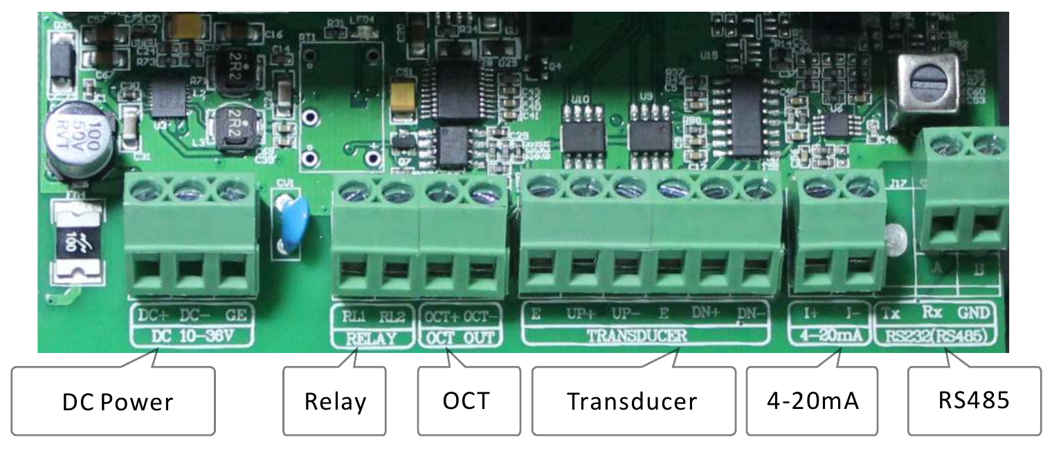
Wiring Diagram
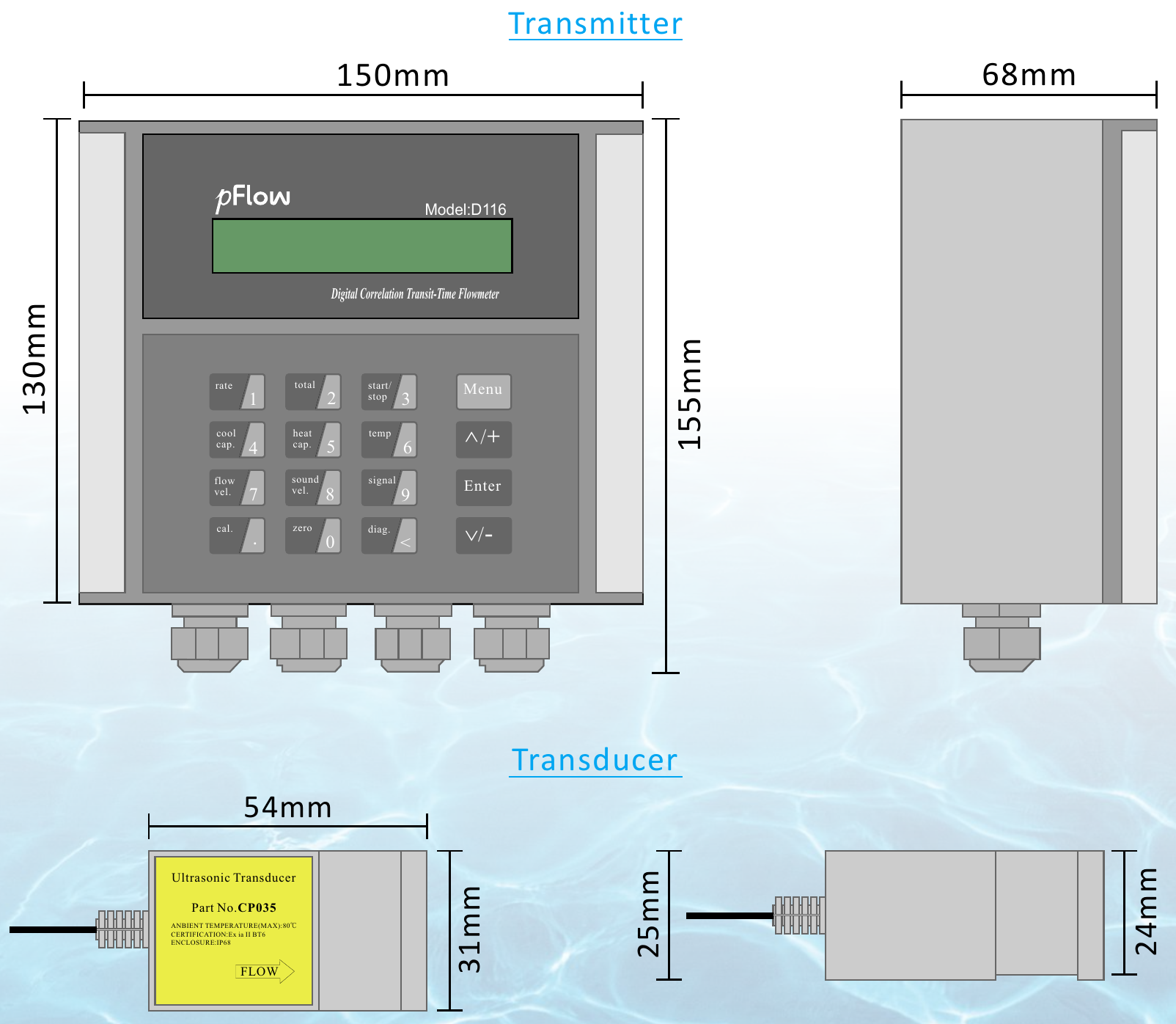
Transmitter and Transducer Dimensions — mm
Transducer Installation Methods
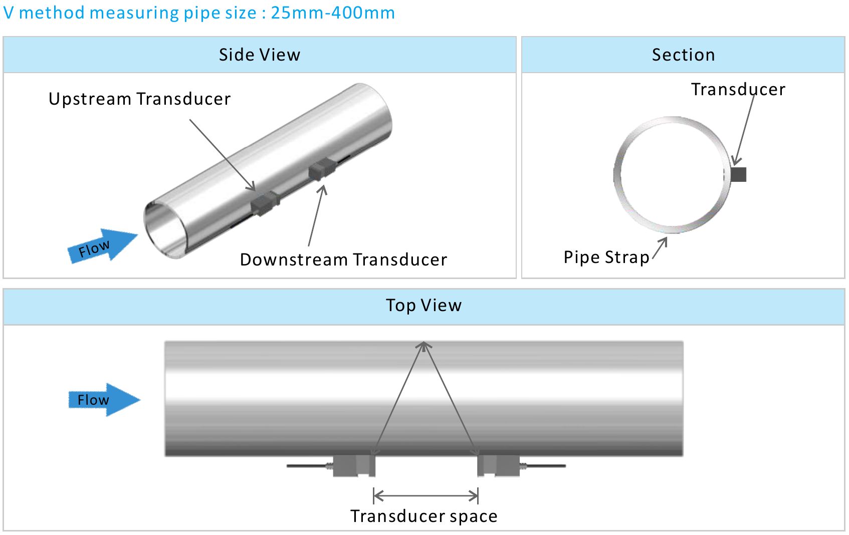
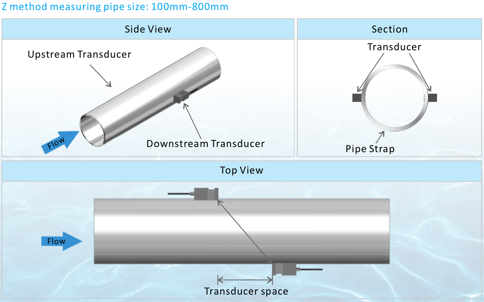
Installation Site Selection
When selecting a measurement site, it is important to select an area where the fluid flow profile is fully developed to guarantee a highly accurate measurement. Use the following guidelines to select a proper installation site:
Choose a section of pipe that is always full of liquid, such as a vertical pipe with flow in the upward direction or a full horizontal pipe.
Ensure enough straight pipe length at least equal to the figure shown below for the upstream and downstream transducers installation.
Ensure that the pipe surface temperature at the measuring point is within the transducer temperature limits.
Consider the inside condition of the pipe carefully. If possible, select a section of pipe where the inside is free of excessive corrosion or scaling.
Build your D116 ordering code
Example — Standard Model: D116-4-CP035-030
Standard flowmeter with Clamp-on transducers, OCT pulse output, Relay output, RS485, 9m cable.