

Liquid Level Gauges
M-Series — Magnetic Level Gauge
Side mounted · Magnetic indication · Optional switches and transmitter
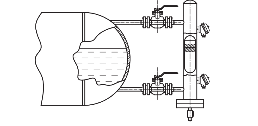
A magnetic float rises and falls inside a non-magnetic chamber connected to the tank at two points. Magnetic coupling operates the external level indicator. Switches and a 4–20 mA transmitter are available for level monitoring and control.
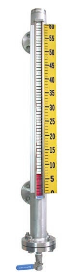 M-Series — Scale indication
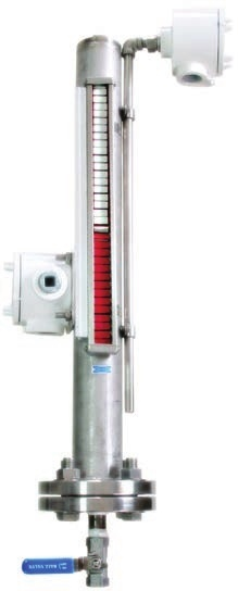 M-Series — Instrumented assembly
Technical data
Application and operating limits
- Application
- Chemical and petrochemical processes, boilers and other industries
- Connections
- ½ in to 3 in; JIS, ANSI and DIN flange ratings; special sizes on request
- PVC / PP chamber
- 5 kg/cm²; 0 to 50°C
- PVDF chamber
- 7 kg/cm²; −30 to 100°C
- Stainless-steel chamber
- 20 kg/cm²; −20 to 150°C
- Special options
- Stainless steel up to 50 kg/cm² or −20 to 300°C on request; titanium-float option up to 100 kg/cm²
- Centre-to-centre length
- Up to 5,500 mm
- Chamber diameter
- Ø50 or Ø60 mm
Limits depend on chamber, float and service. The high-temperature type requires specific gravity of at least 0.8 at 250°C and above. Confirm special pressure and temperature combinations with your enquiry.
Indication and materials
- Level indication accuracy
- ±4 mm
- Transmitter resolution
- ±12 mm standard; ±6 mm on request
- Liquid density
- 500–2,900 kg/m³ for the standard type
- Indicating case
- SS304 standard; hermetically sealed SS304 + PC, IP68, on request
- Indicating strips
- Plastic (PBT) or painted brass; red and white standard, other colours optional
- Indicating float
- Aluminium; separate oil-filled glass indicator tube
- Switch track
- Aluminium
- Orientation
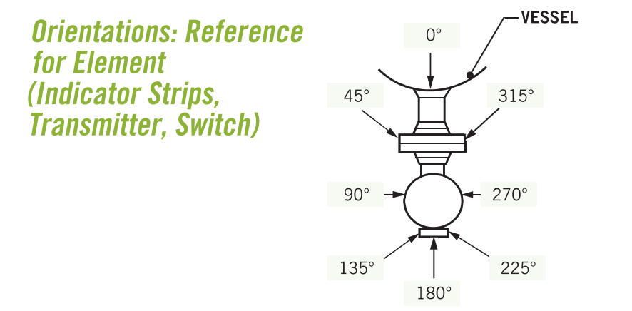
- Adjustable indicating gauge orientation
- Signal options
- 4–20 mA DC, two-wire; HART available
Dimensions and mounting
Side-mounted arrangements from the supplied datasheet. Dimensions are in millimetres. L is the centre-to-centre distance between the tank connections.
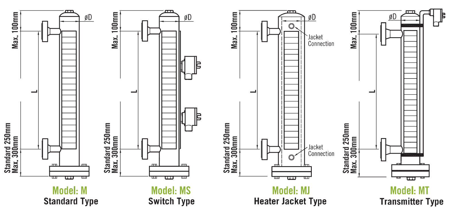
| Model | Arrangement | Dimension / detail |
|---|---|---|
| M | Standard | Chamber Ø50 or Ø60 |
| MS | Switch | External level switches |
| MJ | Heater jacket | Upper and lower jacket connections |
| MT / MTH | Transmitter / HART transmitter | External measuring sensor |
| All side-mounted models | Upper extension | Maximum 100 |
| All side-mounted models | Lower extension | Standard 250; maximum 300 |
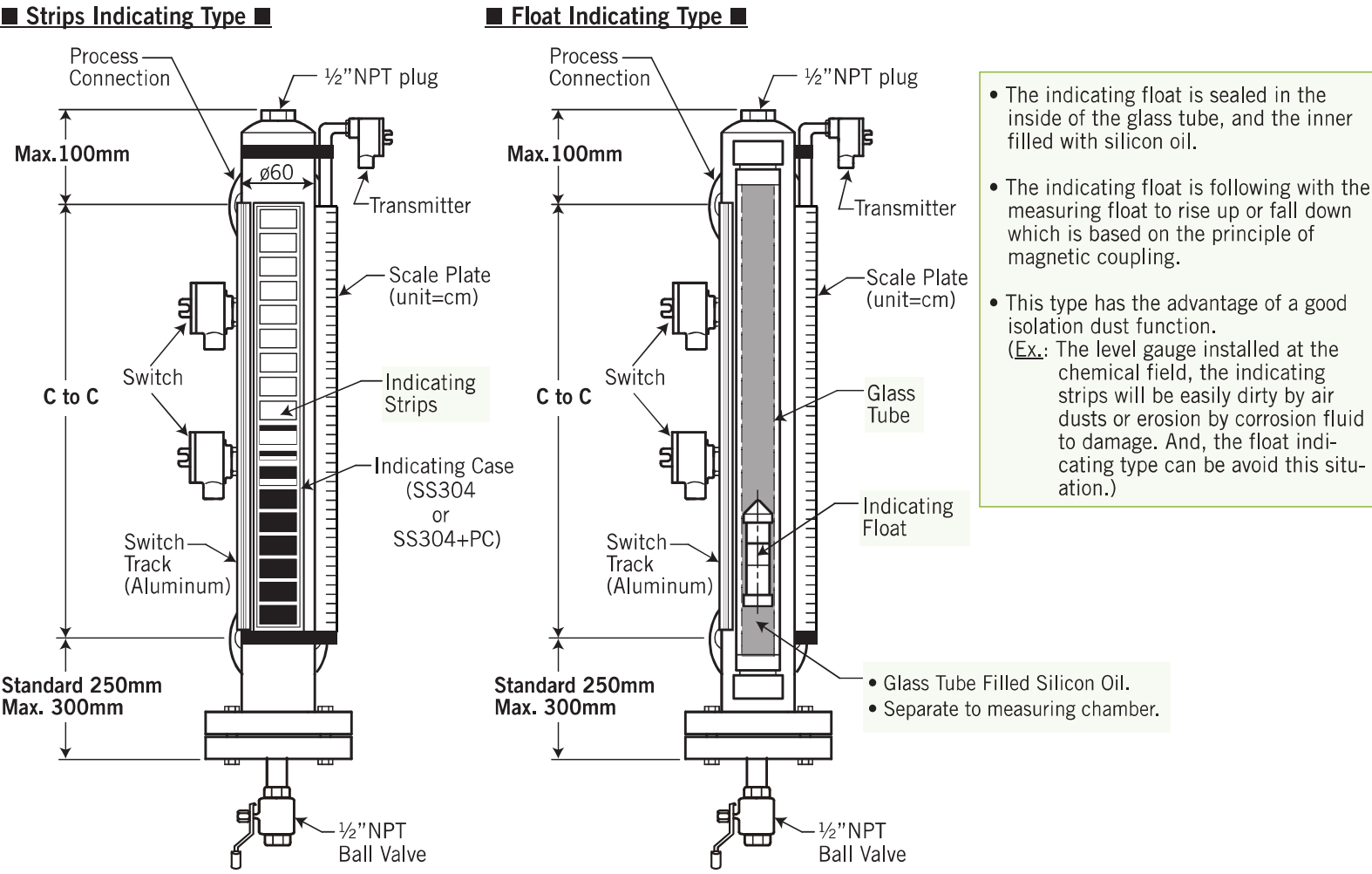
| Feature | Construction |
|---|---|
| Indicating strips | Magnetic coupling operates external strips as the measuring float moves inside the chamber. |
| Indicating float | The aluminium indicating float is sealed in a separate glass tube filled with silicone oil. |
| Vent / drain shown | ½ in NPT plug above; ½ in NPT ball valve below. |
| Detail | Selection |
|---|---|
| Orientation | Specify the indicator, switch and transmitter positions relative to the vessel with your enquiry. |
Switches and transmitter
Level switches
- Micro switch
- MS-1 weatherproof IP66; MWS explosion-proof housing option
- Contacts
- 1 × SPDT; 2 × SPDT at one setting point available
- Micro switch rating
- 3 A / 250 VAC, 5 A / 125 VAC, 4 A / 30 VDC
- Reed switch
- SPST, Form A normally open, bistable
- Reed switch rating
- AC 125 V / 0.5 A; DC 100 V / 10 W; maximum DC 250 V, below 40 mA
Specify each setting height and whether the switch turns ON as the float rises or falls.
Transmitter
- Output / supply
- 4–20 mA DC / 10–30 VDC
- Accuracy / linearity
- ±0.1% F.S. at 23°C / ±0.1% F.S.
- Ambient temperature
- −5 to 70°C
- Operating humidity
- 0–90% RH
- HART option
- Two-wire transmitter with galvanic isolation
Protection and explosion-proof options refer to the specified switch or transmitter assembly. Confirm the required equipment certification with your enquiry.
Ordering information
Choose the side-mounted model and options to build your reference. Enter the liquid specific gravity and centre-to-centre length; for each selected switch point, enter its height and choose Up ON (float rises) or Down ON (float falls).
Specific gravity is dimensionless: 500–2,900 kg/m³ corresponds to approximately 0.5–2.9. Give the operating temperature, pressure, liquid and any special requirements with your enquiry.
The reference follows the PDF sequence: model, connection, rating, wetted parts, case, indicator, switch, points, transmitter, scale, protection, specific gravity, length and LCD. Switch settings are appended.
Specifications are general selection guidance. Confirm materials, connection standards, operating temperature and pressure with Sightflow before placing an order.