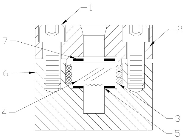
Reflex Liquid Level GaugeAssembly Instructions This unit was assembled at the factory and is ready for installation. The sight glass should be visually checked for any possible damage during shipping. After the unit has been installed and brought to operating conditions, it should be inspected for any possible leakage. REMOVAL OF LENS: Remove the cap screws (1) and remove the retainer cap (2). The o-rings or packing (3) is usually removed with a screw type packing remover. If the unit has been in operation the o-rings or packing will be damaged upon removal and must be replaced to provide a proper seal. The lens (4) can be removed, once the o-rings or packing are removed. SPARE PARTS: The spare parts consist of gaskets, o-rings or packing and lens if needed. Remove any deposits from the bottom seat. Place one gasket (5) on bottom seat. Place lens (4) on gasket. Place the o-rings or packing (3) into the space between the outside of the lens and the inside of the body (6). Place the remaining gasket (7) on top of the lens. Place the retainer cap (2) in position and install the cap screws (1). Tighten down cap screws approx. 30-40 ft-lbs incrementally using proper torquing procedures to ensure even sealing. It is not necessary to achieve metal to metal contact of the body and cap upon assembling the sight glass. Then tighten down the set screws (not shown in drawing) to keep a preload and help prevent loosening of the cap screws. Should leakage occur, loosen the set screws and follow the tightening procedure until leakage has stopped. |
