Sightflow
  • Home
  • Products
    • Sight Glass Windows
      • Just Glass
        • Just Glass
      • Model B Flange
        • Model B Flange Sight Glass Assembly Instruction Video
      • Model B Weld
        • Model B Weld Sight Glass Assembly Instruction Video
      • Model I Flange
        • Model I Flange Sight Glass Assembly Instruction Video
      • Model I Weld
        • Model I Weld Sight Glass Assembly Instructions
      • Model I Slip-On
      • Model I Flange with Teflon® Insert
        • Model I Sight Glass with Teflon Insert Assembly Instructions
      • Model L Flange
        • Model L Flange Sight Glass Assembly Instructions
      • Model L Weld
        • Model L Weld Sight Glass Assembly Instructions
      • Model S
      • X150
      • Bull’s Eye
        • Bull's Eye NPT Sight Glass Assembly Instructions
        • Bulls eye see thru sight assembly
      • Oblong
        • Oblong Sight Glass Assembly Instructions
      • Hinged Closure
      • Manways
      • Type I & II with Threaded Retainer Cap
      • Type III Sight Glass with Sanitary Clamp
    • Sight Flow Indicators
      • NAW-SERIES - Teflon Ball or Rotor
      • NAM-SERIES - With Rotor
      • FW-SERIES Sight Flow indicator
      • T-SERIES Sight Flow Indicator
      • TB series-C Colour-Ball Indication
      • FT-SERIES Indicator/Meter
      • F-SERIES Sight Flow Indicator
      • FS Series Sight Flow Indicator/Meter
      • NAC SERIES Sightflow Indicator
      • SG-SERIES Sight Flow Indicator
      • Bull's Eye See-Thru
      • Bull’s Eye See Thru Flanged
      • Sanitary Full-View
      • Full-View
      • Model B Safesite
      • Model i Safesite
      • Model L Safesite
      • Teflon® Lined Safesite
    • Liquid Level Gauges
      • See-Thru Liquid
        • See-Thru Liquid Level Gauge Assembly Instructions
      • Reflex
        • Reflex Liquid Level Gauge Assembly Instructions
      • Weld Pad
        • Weld Pad Liquid Level Gauge Assembly Instructions
      • Marine Level Gauges (DNV GL)
      • OBLONG Level Gauges
    • Tubular Level Gauges
      • BSP TUBULAR Level Gauges
      • NPT TUBULAR with Guard Rods
      • NL SERIES with Support Protection Rod
      • SL SERIES with Super Guard
      • BL SERIES TUBULAR LEVEL GAUGE
      • Mini Level Gauge (Top Vented)
    • Magnetic Level Gauges
      • M-Series Side Mounted
      • M-Series Top Mounted
      • SN-Series MINI
      • M-Series Switch/Transmitter
    • Rotameters
      • PF Series - Rotameter
      • SM Type Rotameter
      • M-Type Rotameter
      • P-Type Rotameter
      • NP-Type Rotameter
      • NR-Type Rotameter
      • N-Type Rotameter
      • HB Type Rotameter
      • KC Type Rotameter
      • KB Type Rotameter
    • Plastic/Acrylic Flow Meters
      • FBC SERIES - Acrylic
        • FBC - Acrylic Flow Meter
      • MBC SERIES Polycarbonate
      • DS-SERIES Acrylic
      • MDS-SERIES Polycarbonate
      • FAC-SERIES Acrylic
      • FAC200-SERIES Acrylic
      • FAC300-SERIES Acrylic
      • VF100 Acrylic
      • VF200 - Polycarbonate
      • VF300 - Polycarbonate
      • VF350 - Polycarbonate
      • OA Series - Acrylic - OEM
    • Spring Type Flow Meters
      • SF100-SERIES - Spring Type
      • SF200-SERIES - Spring Type
      • SF300-SERIES - Spring Type
      • SF350-SERIES - Spring Type
      • SF400-SERIES - Spring Type
    • Metal Tube Flow Meters
      • BR250S Metal Tube Flow Meter
      • BF300 Metal Tube Flow Meter
      • BF300E Metal Tube Flow Meter
      • MF100E Metal Tube MINI FlowMeter
      • MF200 Metal Tube Flow Meter
      • MF200E Metal Tube FlowMeter
      • DF Series Metal Tube FlowMeter
      • OF100 Series Metal Tube FlowMeter
    • Mass Flow Meters
      • TAF Series Mass FlowMeter
      • ULF Series Mass FlowMeter
      • ULFC Mass Flow Controller
      • TLF Series Mass FlowMeter
      • TLFC Mass Flow Controller
      • TMF Mass FlowMeter
      • TMFC Mass Flow Controller
      • THF Mass FlowMeter
      • TSF Mass FlowMeter
      • ETSF Mass FlowMeter Explosion Proof*
    • Ultrasonic Flowmeters
      • D116 Ultrasonic Flowmeter
      • P116 Portable Ultrasonic Flowmeter
      • D118 Ultrasonic Flowmeter
      • P118i Handheld Ultrasonic Flowmeter
      • D348D Ultrasonic Flowmeter (Picofly)
      • D348D Plus Ultrasonic Flowmeter
      • F148 Ultrasonic Flowmeter
    • Bursting Disk Holders
      • Standard Holder
      • Pre-Loaded Holder
      • Holder SH Lab
        • Holder SH Lab
      • Graphite Holder
    • Bursting Disks
      • Flat Metal Bursting Disks
      • Forward Acting Metal Bursting Disks
      • Reverse Acting Rupture Disks
      • Sanitary Bursting Disks
      • Extruder Bursting Disks
      • One-Way Units Rupture Disks
    • Bursting Disks (Graphite)
      • Graphite Bursting Discs Series G2
      • Graphite Bursting disks Series G3
    • Burst Indicators
      • Burst Indicator Type SVT 02
      • Leakage Sensor Type SVT 05
      • Burst Indicator Type SVT F-ST
      • Low-Pressure Type SVT AM-L
      • Full Metal Burst Indicator
      • Integrated Burst Indicator
    • Tank Protection
    • Tank Breather Valves
      • Pressure & Vacuum Relief
      • Pressure Only Relief Valves
      • Vacuum Only Relief Valves
      • Spring Loaded Relief Valves
      • Pilot Operated Relief Valves
    • Nitrogen Blanketing Valves
      • Nitrogen Blanketing Valves
    • Flame Arresters
      • Deflagration, In-Line Flame Arrester
      • End of Line Deflagration Flame Arresters
      • In-Line Detonation Flame Arresters
      • Vent Combination Arresters
    • Emergency Relief Vents & Manways
      • Pressure Relief Manways
      • Pressure and Vacuum Relief Manway
      • ACCESS MANWAY / CNC 171
    • Tank Fittings
      • Tank Free Vents
      • Rim Vent
    • Pressure Switches
      • PS2000W
  • Resources
    • Instructional Videos
    • Sight Glass Resource Center
    • Fluid Compatibility Table
    • Thread Identificaion Chart
    • White Papers
    • Bursting Disk or Safety Valve?
    • FlowMeters and other cool stuff!
  • Contact Form
    • Contact Form (General)
    • Contact Form (Bursting Disks)
  • Print

Model I Safesite Sight Flow Indicator

Assembly Instructions

Model I Safesite Sight Flow Indicator Assembly

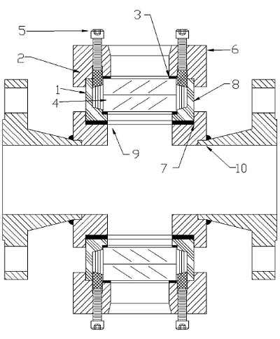
This unit was assembled at the factory and is ready for installation. NOTE: The sight glass should be visually checked for any possible damage during shipping. Alter the unit has been installed; heated and pressurized several times it should be inspected to check for any possible leakage. Ii leakage occurs, follow step (M) until leakage has stopped.

If the lens or packing in the sight glass needs to be replaced alter the unit has been in operation, it is suggested that the packing and gaskets be replaced each time, and the lens be replaced if there are any visual deiects in the glass. When installing parts, reier to steps (A) thru (N).

  • (A) Shut down the operating vessel so there is no pressure in the system where the sight glass is operating. Disassemble the unit by removing the cap screws, cap, compression ring, packing, lens, cushion gaskets, insert cup, and mounting gasket.
     
  • (B) The interior of the housing (1O) and the surface for the mounting gasket must be clean.
     
  • (C) Place the insert cup (1) on a flat surlace, serrated face down.
     
  • (D) The interior oi the insert cup (1) must be clean.
     
  • (E) Place the bottom cushion gasket (7) (largest ID) into position.
     
  • (F) Carefully place the lens (4) on the bottom cushion gasket (7).
     
  • (G) Insert the packing (8) between the lens (4) and the interior wall of the insert cup (l) in a normal packing procedure.
     
  • (H) Place the mounting gasket (9) into the flange housing (10). The insert cup (1) can be set in the flange housing (10).
     
  • (I) Place the one piece compression ring (2) on the packing (8) bevelled side down.
     
  • (J) Place the top cushion gasket (3) (smallest ID), on the lens (4) and inside the l.D. of the compression ring (2).
     
  • (K) Take the cap (6) and set it on the insert cup (l). The compression ring (2) must fit into the groove in the cap (6).
     
  • (L) Bolt the cap (6) in place. Bolt pattern NOT SHOWN for mounting sight glass cap (6) to housing (10).
     
  • (M) Insert the compression adjustment screws (5) and tighten incrementally across diameters. This procedure should be followed until all the screws are tight.
     
  • (N) Occasionally, when pressure is applied, the packing (8) will loosen. Should leakage occur, follow the tightening procedure outlined in step (M), until the leakage has stopped.


Sight Flow Indicators

  • NAW-SERIES - Teflon Ball or Rotor
  • NAM-SERIES - With Rotor
  • FW-SERIES Sight Flow indicator
  • T-SERIES Sight Flow Indicator
  • TB series-C Colour-Ball Indication
  • FT-SERIES Indicator/Meter
  • F-SERIES Sight Flow Indicator
  • FS Series Sight Flow Indicator/Meter
  • NAC SERIES Sightflow Indicator
  • SG-SERIES Sight Flow Indicator
  • Bull's Eye See-Thru
  • Bull’s Eye See Thru Flanged
  • Sanitary Full-View
  • Full-View
  • Model B Safesite
  • Model i Safesite
  • Model L Safesite
  • Teflon® Lined Safesite

Send an email with your requirements to: 

mail@sightflow.com.au

or use our

 Contact form

Let us know of your exact application needs.

Tel: 1800 539 220

If we don't carry it, we'll try to source it!

Mob: 0400 938611

© 2025 Sightflow. All Rights Reserved.

  • Like us on Facebook
  • "Follow us on Twitter
  • Follow our YouTube page
  • +1 Join us on Google Plus
  • Connect on Linkedin
Go Top